Cable support and machining die thereof

A technology for cable brackets and processing molds, which is applied in the bracket field and can solve problems such as disorder, intertwining of cables or optical fibers, etc.

Inactive Publication Date: 2020-04-28
SHENZHEN POWER SUPPLY BUREAU
View PDF4 Cites 0 Cited by
  • Summary
  • Abstract
  • Description
  • Claims
  • Application Information

AI Technical Summary

Problems solved by technology

[0003] Based on this, it is necessary to provide a cable bracket that can hang and place cables or optical fibers separately to solve the above-mention

Method used


Image

  • Cable support and machining die thereof
  • Cable support and machining die thereof
  • Cable support and machining die thereof

Examples


Embodiment Construction

[0027] The technical solutions in the embodiments of the application will be further clearly and completely described below in conjunction with the accompanying drawings, but it should be noted that the following embodiments are only some of the preferred embodiments in the application, and do not involve all examples.

[0028] It should be noted that, in the description of the present application, when an element is referred to as being “fixed” to another element, it may be directly on the other element or there may be an intervening element. When an element is referred to as being "connected to" another element, it can be directly connected to the other element or intervening elements may also be present.

[0029] Unless otherwise defined, all technical and scientific terms used herein have the same meaning as commonly understood by one of ordinary skill in the technical field of the invention. The terms used herein in the description of the present invention are for the pu...


PUM


Abstract

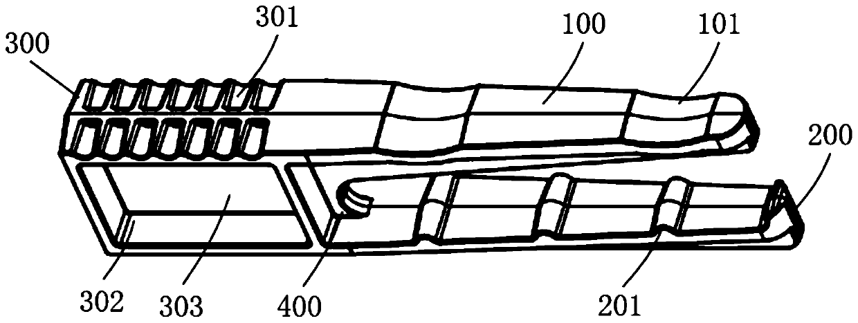
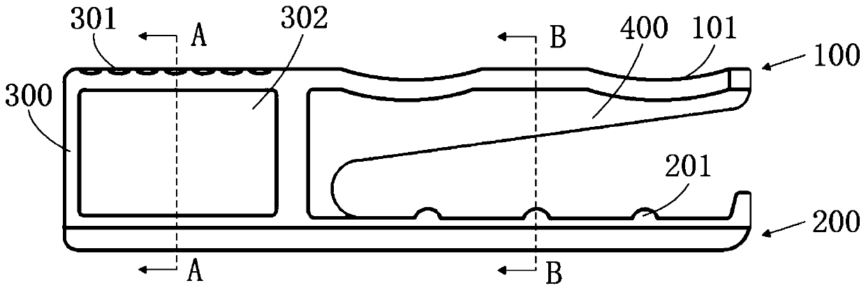
The invention relates to a cable support and a machining die thereof. The cable support comprises an embedded seat, a first bracket and a second bracket; one end of the first bracket is fixedly connected to one end of the embedded seat; a cable placing groove for placing a first cable is formed in the upper surface of the first bracket; one end of the second bracket is fixedly connected to the same end of the embedded seat; the second bracket and the first bracket are located on the same side of the embedded seat; and the second bracket is parallel to the first bracket; a plurality of protrusions are arranged on the upper surface of the second bracket; a second cable is placed between every two adjacent protrusions. According to the cable support and the machining die thereof of the invention, the separate hanging of cables or optical fibers is achieved through the first bracket and the second bracket in the cable support, and the cables or the optical fibers are prevented from being intertwined and disordered.

Description

technical field [0001] The invention relates to the field of brackets, in particular to a cable bracket and a processing mold thereof. Background technique [0002] At present, in the construction of municipal roads, there are trenches or ditches for laying cables or optical fibers on both sides of the road. When laying underground cables or optical fibers, usually in the trench or the main road ditch, prefabricated single bracket crossbar or triangular iron single bracket is used to support the cable or optical fiber, because the structure of single bracket crossbar and single bracket is relatively simple , It is impossible to hang and place the cables or optical fibers separately, resulting in the intertwining and disorder of the laid cables or optical fibers, which makes the intensive planning, design and construction of the municipal departments more difficult in the later stage. Contents of the invention [0003] Based on this, it is necessary to provide a cable hold...

Claims


Application Information

Patent Timeline
IPC IPC(8): H02G9/02G02B6/44G02B6/50C04B26/18B28B7/00
CPCB28B7/0029C04B26/18C04B2111/00844G02B6/4452G02B6/50H02G9/02C04B14/28C04B14/42C04B24/00C04B2103/0013
Inventor 何权政许卫东张斌王京肖明华许晨何旭彬韩小刚成春荣
Owner SHENZHEN POWER SUPPLY BUREAU
Why Eureka
Try Eureka