Continuous free bending precise forming method

A bending and precise technology, applied in the field of continuous free bending precision forming, can solve the problems of difficulty in guaranteeing the precision of bending forming and increasing difficulty of precise forming control, and achieve the effect of simple and feasible method, high production efficiency and reduced production cost

Inactive Publication Date: 2020-05-01
NANJING UNIV OF AERONAUTICS & ASTRONAUTICS
View PDF4 Cites 4 Cited by
  • Summary
  • Abstract
  • Description
  • Claims
  • Application Information

AI Technical Summary

Problems solved by technology

At the same time, it is difficult to guarantee the bending precision
In the three-dimensional free bending forming process of pipes and profiles, the degree of freedom of materials is greater, and the difficulty of precise forming control is increased

Method used


Image

  • Continuous free bending precise forming method
  • Continuous free bending precise forming method
  • Continuous free bending precise forming method

Examples


Embodiment 1

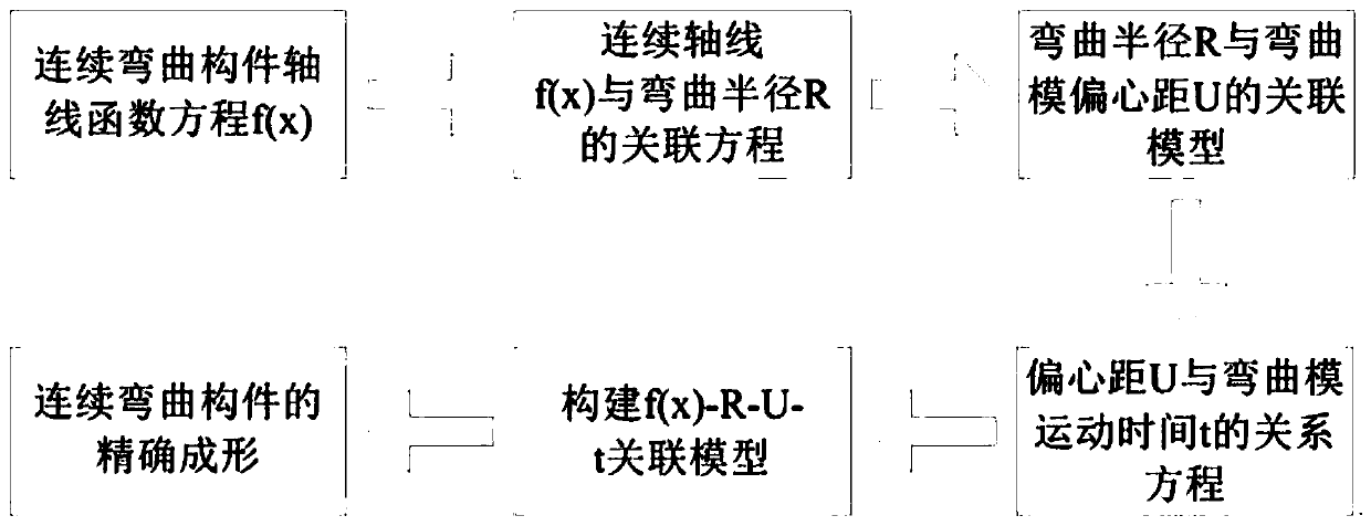
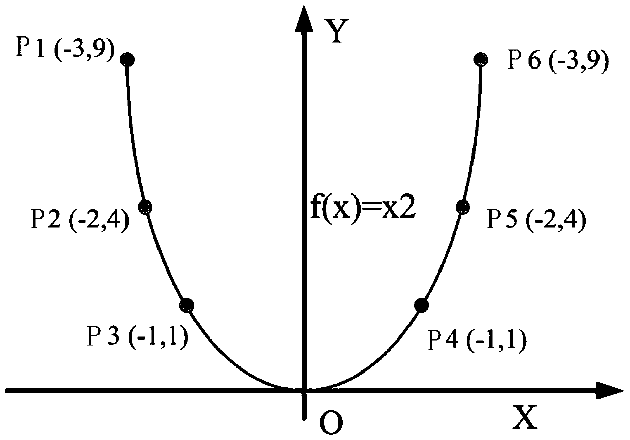
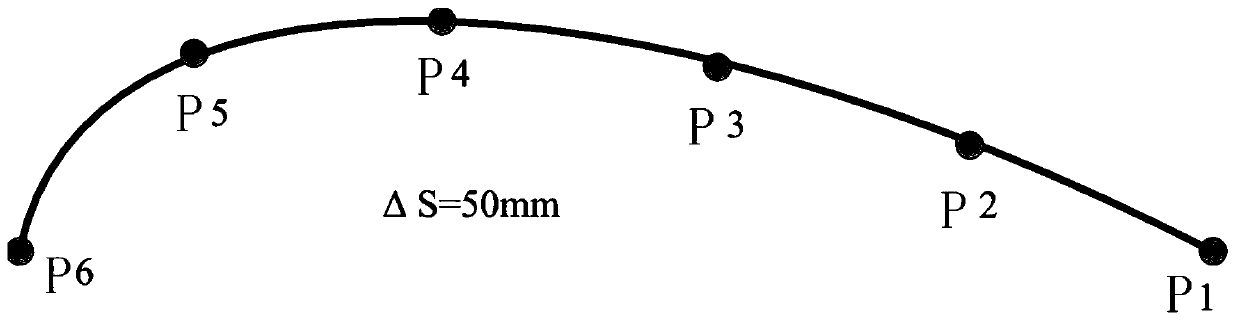
[0024] Such as Figure 1-4 As shown, this embodiment takes the parabolic axis f(x) 1 =x 2 (-3≤x≤3) complex components as an example. Firstly, the bending axis is extracted on the complex bending member, there are n points on the axis, and each point corresponds to a bending radius R n , in the process of free bending, corresponding to an eccentricity U n and time t n , that is, at each time there is a corresponding eccentricity to control the free bending of the parabolic member. In this embodiment, 6 control points are selected on the parabolic axis, and the function relationship f(x) 1 =x 2 To determine the coordinates of the six control points P1 (-3, 9), P2 (-2, 4), P3 (-1, 1), P4 (1, 1), P5 (2, 4), P6 (3 , 9), and calculate the bending radius R n , the eccentricity and movement speed of the bending die are determined through the calculation of each analytical formula of the free bending forming process, so as to determine the motion trajectory, and the free bendin...

Embodiment 2

[0030] The present invention uses a self-defined continuous curve f(x) 2 as an example. Firstly, the bending axis is extracted from the complex curved member, and the bending radius changes with the increase of the arc length, and the bending radius will increase or decrease by 20mm for every 50mm increase in the arc length. The bending radius of the initial point of the curve segment is 260mm, there are n points on the axis, and each point corresponds to a bending radius R n , in the process of free bending, corresponding to an eccentricity U n and time t n , that is, there is a corresponding eccentricity at each time to control the free bending forming of complex components. For example, select 6 control points on the custom complex axis, and use the function relationship f(x) 2 The law to determine the bending radius R of the six control points n , respectively for R 1 =260mm, R 2 =240mm, R 3 =220mm, R 4 = 200mm, R 5 =180mm, R 6 =160mm, the eccentricity and movem...


PUM


Abstract

The invention discloses a continuous free bending precise forming method. The method comprises the following steps of firstly, establishing a relation equation of a continuous axis f (x) and a bendingradius R, and determining the bending radius R of the real-time position of the axis; and establishing a correlation model between the real-time bending radius R of the pipe and the eccentric distance U of the bending die through a free bending technology, further establishing a relation between an equation of an axis and free bending parameters, completely constructing a correlation model amongf (x)-R-U-t through a relation equation between the eccentric distance U and the movement time t of the bending die, and realizing the accurate forming of complex continuous bent components. Accordingto the method, production efficiency is improved.

Description

technical field [0001] The invention relates to a flexible manufacturing method of metal components, in particular to a continuous free bending precise forming method. Background technique [0002] Complex curved components have extensive and important applications in nuclear energy equipment, aerospace and other fields. In the actual forming process, complex axes make forming more difficult, especially for complex curved members with continuously variable curvature. At the same time, the bending forming accuracy is also difficult to guarantee. In the three-dimensional free bending forming process of pipes and profiles, the degree of freedom of materials is greater, and the difficulty of precise forming control is increased. For continuous bending complex components, the forming accuracy has a great influence on the forming quality of components, so it is necessary to propose an accurate forming method to control the forming accuracy of complex bending components. Conten...

Claims


Application Information

Patent Timeline
Patent Type & Authority Applications(China)
IPC IPC(8): B21D11/00
CPCB21D11/00B21D7/12B21D7/085B21D11/02G05B13/04
Inventor 郭训忠魏文斌陶杰王辉
Owner NANJING UNIV OF AERONAUTICS & ASTRONAUTICS
Why Eureka
Try Eureka