Vertical-positioning perforating device used for machining

A technology of mechanical processing and punching device, which is applied in the field of mechanical parts processing, which can solve problems such as difficult positioning, crooked punching, and part position deviation, and achieve the effect of high punching accuracy

Inactive Publication Date: 2020-05-01
WEST ANHUI UNIV
View PDF7 Cites 4 Cited by
  • Summary
  • Abstract
  • Description
  • Claims
  • Application Information

AI Technical Summary

Problems solved by technology

[0003] Before the drilling operation, the workpiece needs to be clamped and positioned. Since the external dimensions of the workpiece are not conventional structures, it is often difficult to perform firm positioning when positioning workpieces of different shapes. During the drilling work, due to the vibration intensity If it is too large, it will cause the position of the parts to shift, resulting in the occurrence of perforated holes
Due to the inability to effectively control the position of the punched workpiece firmly and stably, resulting in an increase in the punching error

Method used


Image

  • Vertical-positioning perforating device used for machining
  • Vertical-positioning perforating device used for machining
  • Vertical-positioning perforating device used for machining

Examples


Embodiment 1

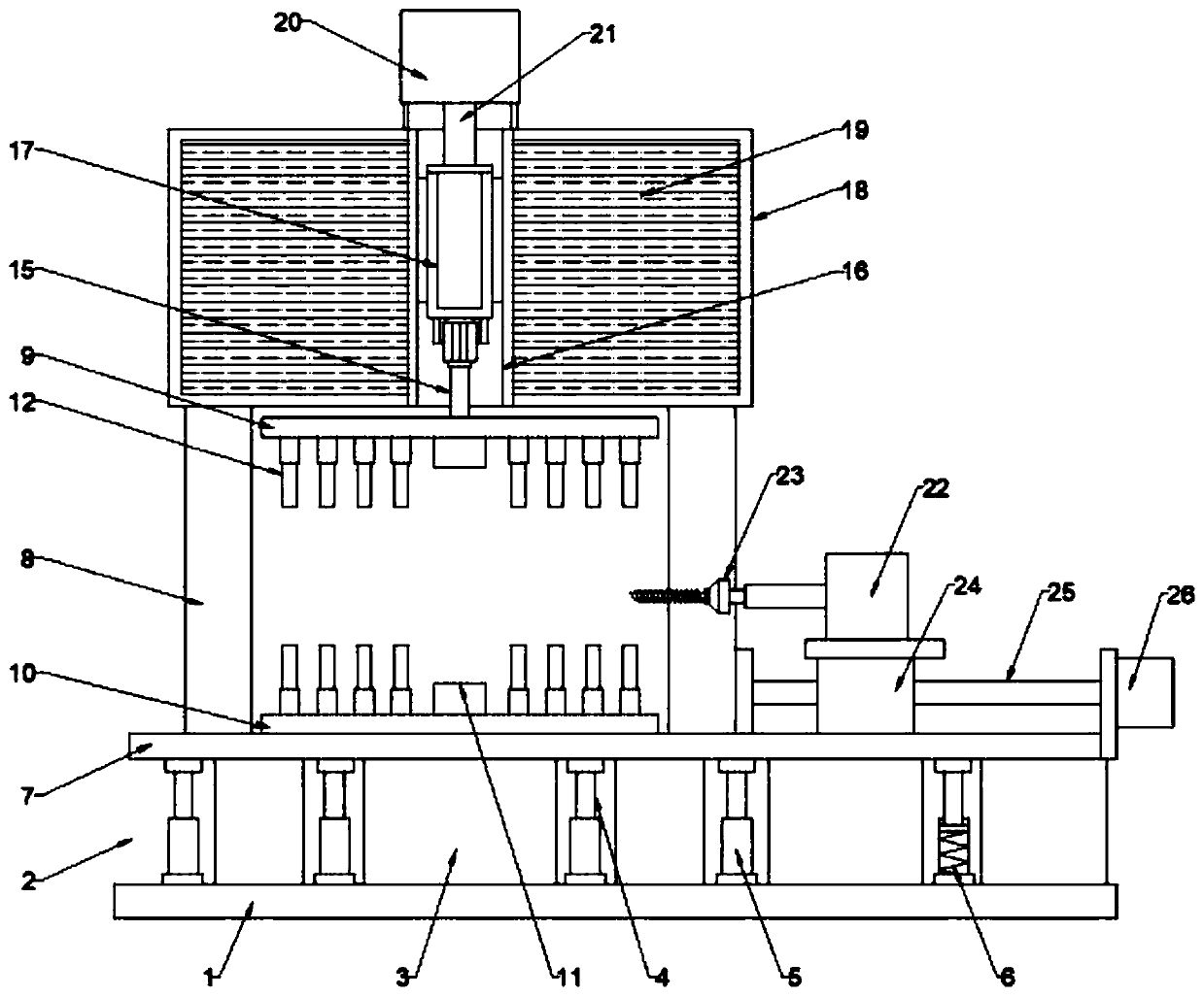
[0025] see Figure 1 ~ Figure 2 , a kind of drilling device for machining with vertical positioning, comprising a workbench 7, a support frame 8, an upper positioning plate 9, a lower positioning plate 10, a noise reduction box 18 and a drilling bit 23, the bottom of the workbench 7 is installed There is a shock-absorbing seat 2, and the shock-absorbing seat 2 includes a base plate 1, a shock-absorbing rubber block 3, a shock-absorbing column 4, a shock-absorbing sleeve 5 and a shock-absorbing spring 6, wherein the base plate 1 is arranged below the workbench 7, and the base plate 1 and A shock-absorbing rubber block 3 is fixed between the workbenches 7. A shock-absorbing sleeve 5 is welded on the base plate 1. A shock-absorbing column 4 is arranged inside the shock-absorbing sleeve 5. Between the shock-absorbing column 4 and the shock-absorbing sleeve 5 A shock-absorbing spring 6 is arranged between them, and the top of the shock-absorbing column 4 is fixed on the workbench 7...

Embodiment 2

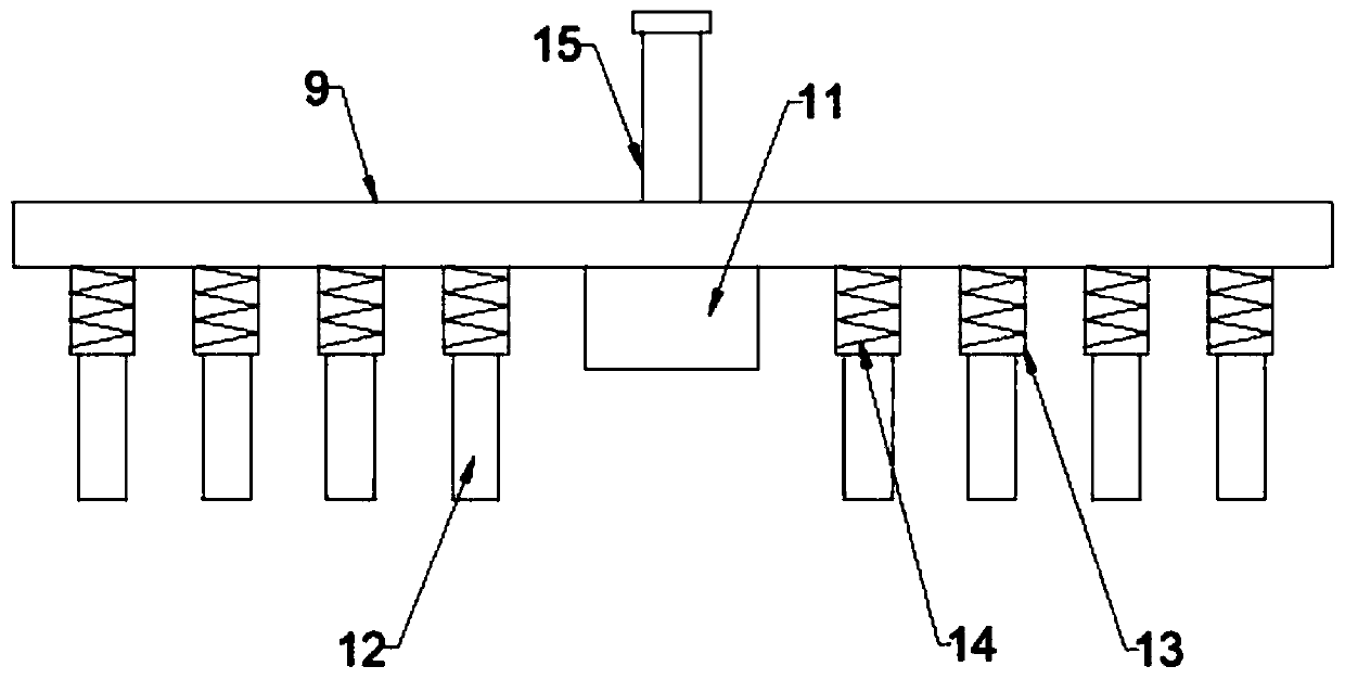
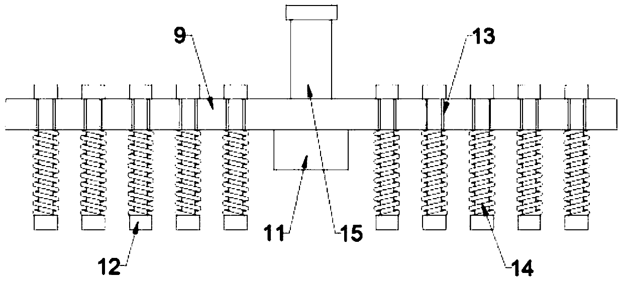
[0031] see figure 1 Shown, a kind of vertically positioned mechanical processing drilling device includes a workbench 7, a support frame 8, an upper positioning plate 9, a lower positioning plate 10, a noise reduction box 18 and a drilling bit 23, and the workbench 7 A support frame 8 is installed on the top of the support frame 8, and a noise reduction box 18 is connected to the top of the support frame 8. A sound-absorbing panel 19 is installed in the noise reduction box 18, and a vertical chute 16 is arranged in the middle of the noise reduction box 18. A slider 17 is provided for sliding, the top of the slider 17 is connected to the hydraulic cylinder 20 through the hydraulic rod 21, the hydraulic cylinder 20 is fixed on the top of the noise reduction box 18, the bottom of the slider 17 is connected to the upper positioning plate 9 through the pressing rod 15, and the upper positioning plate 9 The middle part of the bottom end is connected with a clamping block 11, the low...


PUM


Abstract

The invention discloses a vertical-positioning perforating device used for machining and belongs to the technical field of mechanical part machining. The problem that clamping positioning is difficultwhen the outline dimension or performance of a workpiece is changed is solved. The technical scheme includes that the perforating device comprises a workbench, a supporting frame, an upper positioning plate, a lower positioning plate, a noise-reduction box and a perforating drill bit; a damping base is mounted at the bottom of the workbench; the supporting frame is mounted on the workbench; the top of the supporting frame is connected with the noise-reduction box; a sliding block is arranged in a vertical sliding groove in a sliding mode; the top of the sliding block is connected with a hydraulic block through a hydraulic rod; the bottom of the sliding block is connected with the upper positioning plate through a jacking pressure rod; the lower positioning plate is arranged under the upper positioning plate; and the hydraulic cylinder drives the sliding block to move, so that the upper positioning plate is driven to move, the upper positioning plate is matched with the lower positioning plate, the workpiece is clamped by means of clamping blocks and clamping rods, the perforating device is applicable to clamping and fixing of workpieces in different shapes, perforating operation on the workpiece is achieved through the perforating drill bit, operation is convenient and fast, and the perforating precision is high.

Description

technical field [0001] The invention relates to the technical field of machining of mechanical parts, in particular to a vertical positioning drilling device for machining. Background technique [0002] Machining refers to the process of changing the shape or performance of a workpiece through a mechanical device. The punching device is a common device in the process of machining. It is widely used, mainly for punching raw materials. [0003] Before the drilling operation, the workpiece needs to be clamped and positioned. Since the outer dimensions of the workpiece are not conventional structures, it is often difficult to perform firm positioning when positioning workpieces of different shapes. During the drilling work, due to the vibration intensity If it is too large, it will cause the position of the parts to shift, resulting in the occurrence of perforated holes. Since the position of the punched workpiece cannot be effectively and stably controlled, the punching error ...

Claims


Application Information

Patent Timeline
IPC IPC(8): B23B39/00B23Q3/08B23Q11/00
CPCB23B39/00B23Q3/082B23Q11/0039B23Q11/0096
Inventor 王洪新张鹏许文雷孙宇航吴立业
Owner WEST ANHUI UNIV
Why Eureka
Try Eureka