
Controllable soluble sleeve blanking plug and under-pressure-free oil pipe well descending method

A plug and casing technology, applied in the field of oil and gas well fracturing reconstruction, can solve the problems of high operation cost, long operation period, high construction risk, etc., and achieve the effect of saving operation cost and shortening construction period

Pending Publication Date: 2020-05-01
PETROCHINA CO LTD
View PDF0 Cites 3 Cited by
  • Summary
  • Abstract
  • Description
  • Claims
  • Application Information

AI Technical Summary

Problems solved by technology

At present, the operation has the disadvantages of high construction risk, high operation cost and long operation cycle

Method used


Image

  • Controllable soluble sleeve blanking plug and under-pressure-free oil pipe well descending method

Examples


Embodiment 1

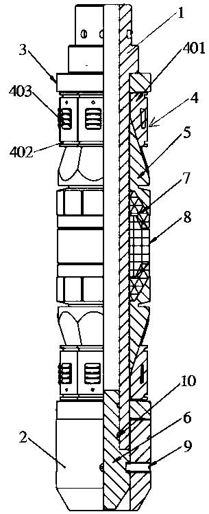
[0029] refer to figure 1 , the embodiment of the present invention proposes a controllable dissolvable casing plug, including: a mandrel 1, two pressure rings 3, two sets of slip assemblies 4, two taper sleeves 5 and a plug 6; the mandrel The upper end of 1 can be connected with the setting device, and the lower end of mandrel 1 is connected with tailstock 2 through external thread; two pressure rings 3 are respectively set on the upper and lower parts of mandrel 1, and the pressure ring 3 set on the lower part of mandrel 1 Lean against the upper end surface of the tailstock 2; two sets of slip assemblies 4 are set opposite to each other in the opening direction, the upper part of one set of slip assemblies 4 leans against the lower end surface of a pressure ring 3, and the lower part of one set of slip assemblies 4 Lean against the upper end surface of a pressure ring 3; two taper sleeves 5 are respectively fitted on the mandrel 1, and the taper surface of each taper sleeve 5...

Embodiment 2

[0032] refer to figure 1 , On the basis of Example 1, the mandrel 1 is made of magnesium-aluminum alloy, and the mandrel 1 is sprayed with a waterproof coating except for the part where the plug 6 is assembled.

[0033] The mandrel 1 is made of magnesium-aluminum alloy, which will slowly dissolve when exposed to water. After the plug 6 is installed at the bottom of the mandrel 1, a waterproof coating is sprayed on the surface and inside of the mandrel 1, so that the invention is controllable and After the melting casing plug is set and sealed in the oil well casing, high-pressure liquid is injected into the oil well casing after the tubing is lowered. After the plug 6 at the lower end of the mandrel 1 is separated from the mandrel 1, the place where the plug 6 is installed on the mandrel 1 is exposed. Under the liquid environment, the mandrel 1 can start to dissolve until it completely disappears, which will not affect the next step of construction.

Embodiment 3

[0035] refer to figure 1 , On the basis of Example 1, the taper sleeve 5 is made of magnesium-aluminum alloy, and the outer surface of the taper sleeve 5 is sprayed with a waterproof coating.

[0036] The taper sleeve 5 is installed on the mandrel 1 and then sprayed with a waterproof coating. When the mandrel 1 dissolves, the inner surface of the taper sleeve 5 in contact with the mandrel 1 is exposed to the liquid environment, and the taper sleeve 5 begins to dissolve until it is completely disappear.


PUM


Abstract

The invention provides a controllable soluble sleeve blanking plug. The controllable soluble sleeve blanking plug comprises a mandrel, two pressing rings, two sets of slip assemblies, two taper sleeves, a rubber sleeve assembly and a plug, wherein the upper end of the mandrel can be connected with a setting device, the lower end of the mandrel is connected with a tailstock through external threads, the two pressing rings sleeve the upper part and the lower part of the mandrel correspondingly, the pressing ring sleeving the lower part of the mandrel leans against the upper end surface of the tailstock, the opening directions of the two sets of slip assemblies are oppositely arranged, the upper part of the one set of slip assembly leans against the lower end surface of the corresponding pressing ring, the lower part of the other one set of slip assembly leans against the upper end surface of the corresponding pressing ring, the two taper sleeves sleeve the mandrel, the conical surface ofeach taper sleeve extends into the inside of the corresponding set of slip assembly, the rubber sleeve assembly is arranged between the two taper sleeves, the upper end of the plug extends into the lower port of the mandrel, and a shear pin is connected between the side wall of the lower end of the plug and the tailstock. The invention further provides an under-pressure-free oil pipe well descending method which is implemented by adopting the controllable soluble sleeve blanking plug.

Description

technical field [0001] The invention belongs to the technical field of fracturing reconstruction of oil and gas wells, and in particular relates to a controllable soluble casing plug and a method for running a pressure-free oil pipe into a well. Background technique [0002] At present, the multi-layer and multi-stage multi-stage fracturing construction of limited-stage and infinite-stage casing sliding sleeves carried out in China needs to be carried out under pressure to enter the tubing for production after the fracturing construction is completed. At present, this operation has the disadvantages of high construction risk, high operation cost and long operation period. As a result, it is urgent to design a casing plug to avoid the risk of drilling under pressure in the later stage, save construction costs, shorten the construction period, and lay the foundation for the further large-scale application of bare casing fracturing technology. Contents of the invention [00...

Claims


Application Information

Patent Timeline
Patent Type & Authority Applications(China)
IPC IPC(8): E21B33/12E21B23/04
CPCE21B23/04E21B33/12
Inventor 胡开斌李宪文张华光赵广民张文星薛晓伟邵媛任勇张安康韩巧荣
Owner PETROCHINA CO LTD
Learn More