Fan installing structure and household appliance with same
An installation structure and technology for household appliances, which are applied in the directions of household heating, household heating, machines/engines, etc., can solve problems such as noise, and achieve the effect of simple fixing method and improving assembly efficiency.
- Summary
- Abstract
- Description
- Claims
- Application Information
AI Technical Summary
Problems solved by technology
Method used
Image
Examples
Embodiment 1
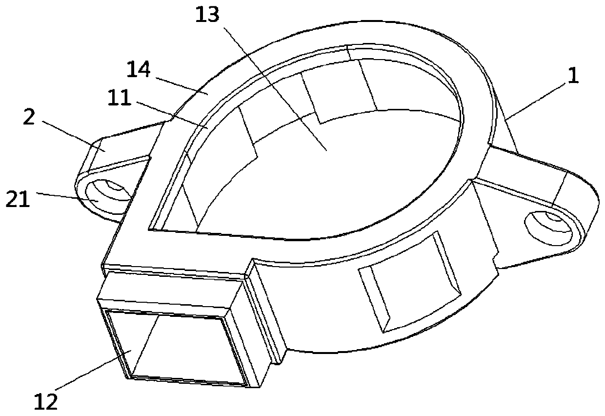
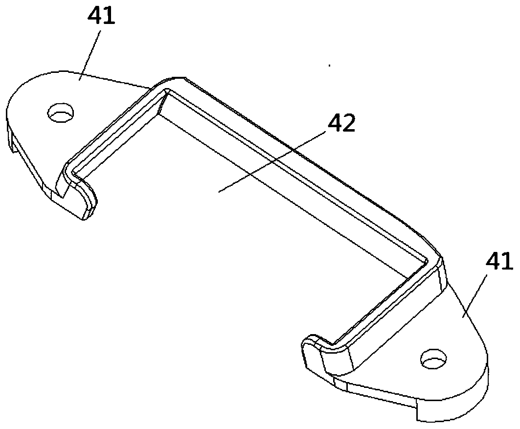
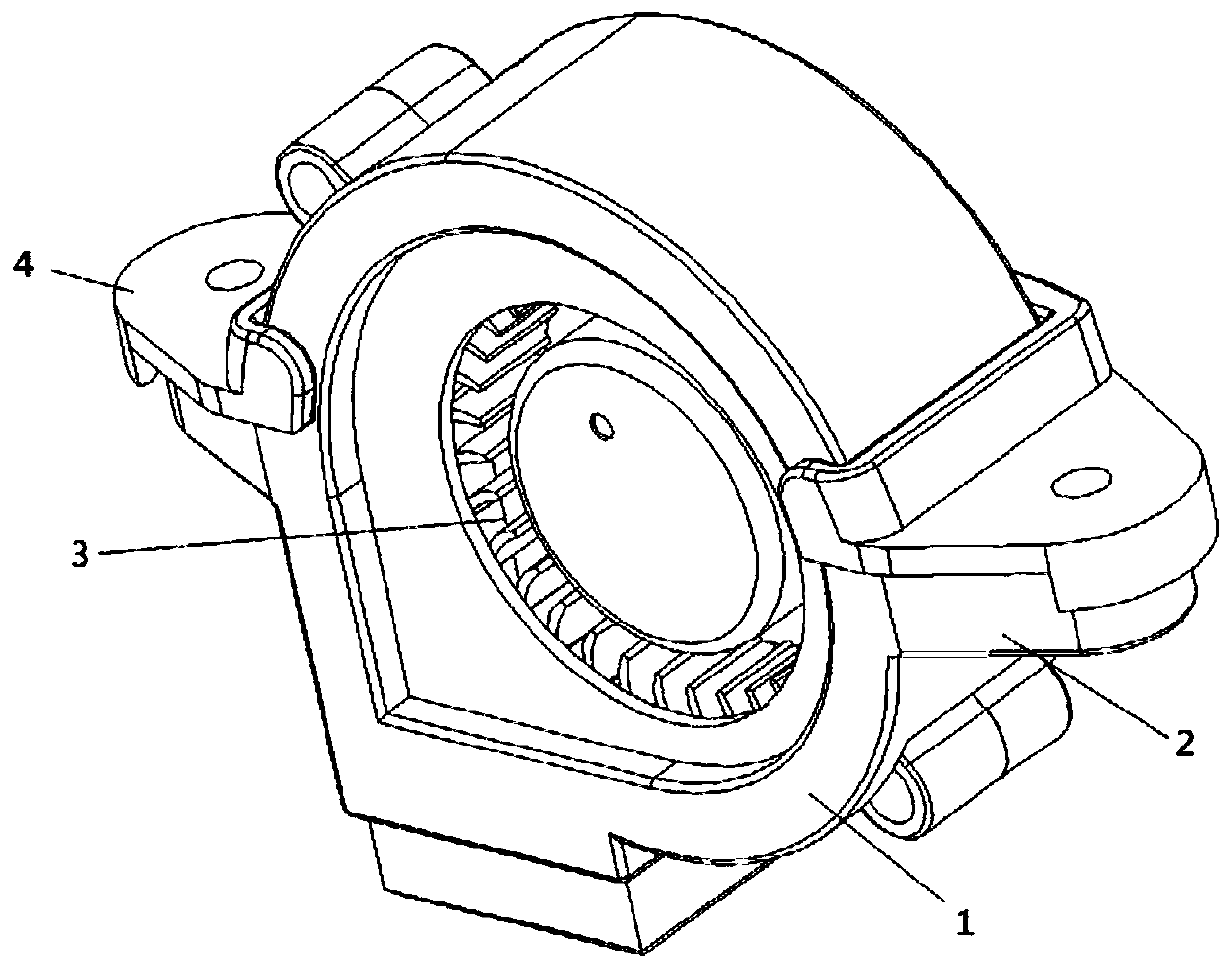
[0049] Figure 1 to Figure 3As shown, a fan installation structure provided in this embodiment includes a first buffer body 1, which is coated on the fan 3, and is provided with an air inlet 11 and an air outlet 12 corresponding to the fan 3; the second buffer body 2, It is arranged on the first buffer body 1 , and when installed with the fan 3 , the second buffer body 2 and the installation surface of the fan 3 are attached to each other.
[0050] The fan installation structure provided in this embodiment is mainly used to reduce the noise generated by the vibration between the fan 3 and the base on which the fan 3 is installed. The implementation object of the fan installation structure described in the following is mainly the fan in the humidifier. Of course, the above-mentioned fan installation structure can also be used in some other electrical equipment, such as the fan in the computer mainframe, the fan in the bladeless fan, etc.
[0051] It should be explained that th...
Embodiment 2
[0070] Such as Figure 4 to Figure 5 As shown, it is a household appliance provided in this embodiment, specifically a humidifier, which includes the fan installation structure described in Embodiment 1 above, and a base 5 on which the fan installation structure is installed.
[0071] Such as Figure 4 As shown in , the base 5 is processed and formed with a mounting seat 51, such as Figure 5 As shown in , the second buffer body 2 is arranged on the upper end surface of the mounting seat 51, the first pressing part 41 of the pressing part 4 is installed on the upper end surface of the second buffer body 2, and the fixed fan 3 When it is on the base 5, a corresponding mounting hole is processed on the mounting seat 51. After the via hole on the first connecting part 21 corresponds to the mounting hole, the second buffer body is fitted on the mounting seat 51. The pressing part 4 , the second buffer body 2 and the fan 3 are fixed on the mounting seat 51 together.
[0072] Suc...
PUM
 Abstract
Description
Claims
Application Information
 - R&D
- Intellectual Property
- Life Sciences
- Materials
- Tech Scout
- Unparalleled Data Quality
- Higher Quality Content
- 60% Fewer Hallucinations
Browse by: Latest US Patents, China's latest patents, Technical Efficacy Thesaurus, Application Domain, Technology Topic, Popular Technical Reports.
© 2025 PatSnap. All rights reserved.Legal|Privacy policy|Modern Slavery Act Transparency Statement|Sitemap|About US| Contact US: help@patsnap.com


