
Pneumatic sealing combined control valve

A combined control and pneumatic sealing technology, applied to valve details, valve devices, engine components, etc., can solve problems such as wear and valve seal failure, and achieve the effects of simplified structure, consistent abutment strength, and long service life

Active Publication Date: 2020-05-01
ZHEJIANG ZHONGDE AUTOMATIC CONTROL VALVE
View PDF8 Cites 2 Cited by
  • Summary
  • Abstract
  • Description
  • Claims
  • Application Information

AI Technical Summary

Problems solved by technology

[0004] However, in the long-term use of the valve structure in the above patent, the O-shaped ball valve and the sealing ring will still wear rapidly during the long-term use, resulting in valve seal failure and wear, causing the medium to accumulate in the cavity of the valve.

Method used


Image

  • Pneumatic sealing combined control valve
  • Pneumatic sealing combined control valve
  • Pneumatic sealing combined control valve

Examples


Embodiment 1

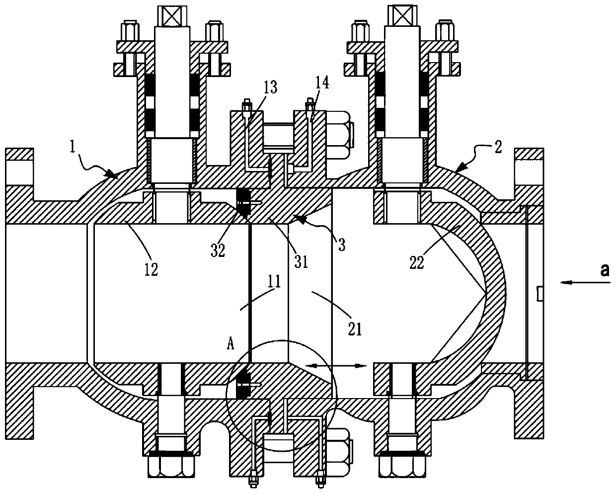
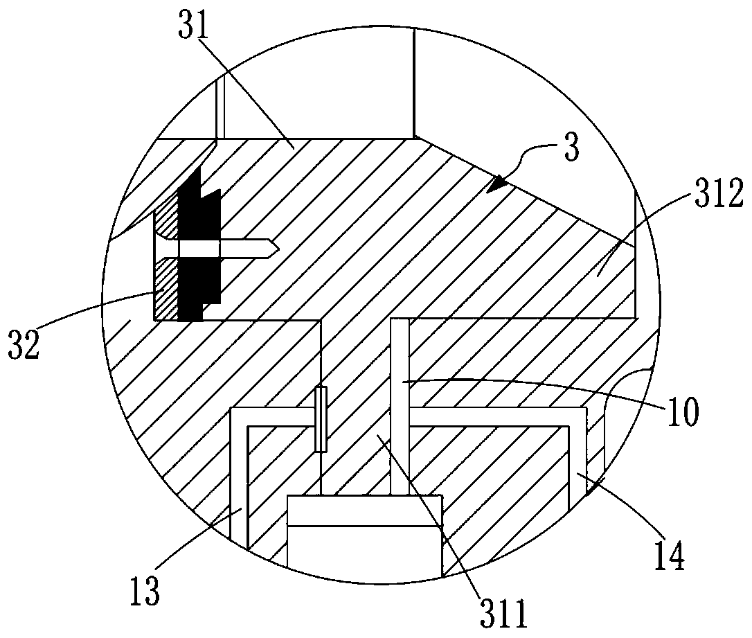
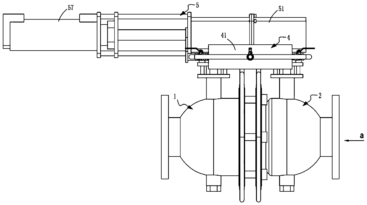
[0046] Such as Figure 1 to Figure 3 As shown, a pneumatic sealing combination control valve includes a sealing valve 1 and a material retaining valve 2, the feed port 11 of the sealing valve 1 communicates with the discharge port 21 of the material retaining valve 2, and the sealing valve 1 is provided with a spherical first valve core 12, and the said blocking valve 2 is provided with a partially spherical "V"-shaped notch-shaped second valve core 22, which also includes:

[0047] The floating sealing mechanism 3, the floating sealing mechanism 3 is arranged at the connection position between the sealing valve 1 and the material blocking valve 2, which includes a piston 31 that reciprocates along the medium flow direction a in the sealing valve 1 and is installed on The sealing valve seat 32 on the piston 31, the sealing valve seat 32 moves with the piston 31 whenever the piston 31 moves, and it abuts and seals against the first valve core 12;

[0048] Pneumatic mechanism 4...


PUM


Abstract

The invention relates to the technical field of valve structures, and particularly discloses a pneumatic sealing combined control valve. The control valve comprises a sealing valve and a stop valve, wherein a feeding port of the sealing valve communicates with a discharging port of the stop valve, a spherical first valve element is arranged in the sealing valve, a partially spherical V-shaped notch-shaped second valve element is arranged in the stop valve, and the control valve further comprises a floating sealing mechanism, a pneumatic mechanism and an executing mechanism. According to the control valve, the stop valve with shearing force is firstly closed to form blocking, then the sealing valve is used for sealing, and finally a floating sealing valve seat abuts against and makes contact with the first valve element in the sealing valve, so that comprehensive sealing is achieved, the sealing valve seat is controlled by the pneumatic mechanism to abut against and get away from the first valve element, in the rotating process of the first valve element, the first valve element does not make contact with the sealing valve seat, abrasion of the sealing valve seat is avoided, and thetechnical problem that valve sealing fails due to abrasion of the sealing valve seat is solved.

Description

technical field [0001] The invention relates to the technical field of gate structures, in particular to a pneumatic sealing combined control valve. Background technique [0002] When the valve is used in high-temperature solid particles or powdery media such as slag powder and coal powder, the slag powder state medium will accumulate in the valve cavity between the valve seats during operation, causing friction between the valve core and the medium and scratching the spherical surface , causing the valve to leak, and under the condition of high pressure difference, the internal parts of the valve will be washed out quickly. The medium is easy to accumulate in the cavity of the valve body and block the inner cavity of the valve, resulting in increased valve torque, stuck ball, improper valve switch, and damaged sealing surface. Under high pressure, when the valve is not closed tightly, the pipeline medium will The throttling phenomenon is formed, and the valve is severely w...

Claims


Application Information

Patent Timeline
Patent Type & Authority Applications(China)
IPC IPC(8): F16K5/06F16K5/08F16K31/122F16K31/44F16K31/53
CPCF16K5/0647F16K5/08F16K31/122F16K31/44F16K31/53
Inventor 粟飞张忠敏张中良李俊杨月富黄宝杰
Owner ZHEJIANG ZHONGDE AUTOMATIC CONTROL VALVE
Learn More