System and method for increasing transceiving separation backscatter communication excitation distance

A technology of backscattering and radio frequency excitation, which is applied in the transmission system, radio transmission system, electrical components, etc., can solve the problems such as the reduction of signal-to-noise ratio of reflected signals, increase the excitation distance, reduce the probability of system saturation, and improve the dynamic range effect

Active Publication Date: 2020-05-01
CHENGDU UNIV
View PDF8 Cites 2 Cited by
  • Summary
  • Abstract
  • Description
  • Claims
  • Application Information

AI Technical Summary

Problems solved by technology

[0004] Aiming at the above-mentioned deficiencies in the prior art, the present invention provides a system and method for increasing the excitation distance of the separated backscatter communication for sending and receiving, which solves the problem that the original radio frequency excitation signal transmitted by the exciter in the backscatter communication becomes the interference signal of the receiver and the The limitations of errors such as phase noise, frequency offset, and spatial multipath lead to a decrease in the signal-to-noise ratio of terminal reflected signals, thereby limiting the distance of the backscatter communication system

Method used


Image

  • System and method for increasing transceiving separation backscatter communication excitation distance
  • System and method for increasing transceiving separation backscatter communication excitation distance
  • System and method for increasing transceiving separation backscatter communication excitation distance

Examples


Embodiment 1

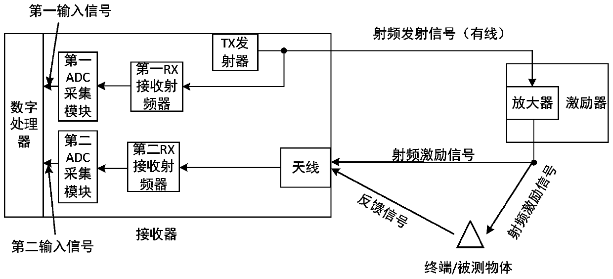
[0073] Such as figure 1 As shown, the receiver includes: a digital processor, a first ADC acquisition module, a second ADC acquisition module, a first RX receiving radio frequency device, a second RX receiving radio frequency device, a TX transmitter and an antenna;

[0074] The digital processor is respectively connected with the output end of the first ADC acquisition module and the output end of the second ADC acquisition module;

[0075] The input end of the first ADC acquisition module is connected to the output end of the first RX receiving radio frequency device;

[0076] The input end of the second ADC acquisition module is connected to the output end of the second RX receiving radio frequency device;

[0077] The output end of the TX transmitter is connected to the input end of the first RX receiving radio frequency device;

[0078] The input terminal of the second RX receiving radio frequency device is connected to the antenna;

[0079] The exciter includes: an am...

Embodiment 2

[0114] Such as Figure 4 As shown, the receiver includes: a digital processor, a first ADC acquisition module, a second ADC acquisition module, a first RX receiving radio frequency device, a second RX receiving radio frequency device, a TX transmitter, a transmitting antenna and a receiving antenna;

[0115] The digital processor is respectively connected with the output end of the first ADC acquisition module and the output end of the second ADC acquisition module;

[0116]The input end of the first ADC acquisition module is connected to the output end of the first RX receiving radio frequency device;

[0117] The input end of the second ADC acquisition module is connected to the output end of the second RX receiving radio frequency device;

[0118] The output end of the TX transmitter is respectively connected with the input end of the first RX receiving radio frequency device and the transmitting antenna;

[0119] The input terminal of the second RX receiving radio freque...


PUM


Abstract

The invention discloses a system and a method for increasing a transceiving separation backscatter communication excitation distance. In the system and the method, the exciter utilizes a repeater architecture to enable an excitation signal transmitted by the exciter and a carrier signal transmitted by the receiver to have high correlation, so that errors such as corresponding phase noise, frequency spectrum and the like are reserved in the excitation signal received by the receiver. The receiver is divided into two paths to receive a carrier signal transmitted by the receiver, an excitation signal transmitted by the exciter and an attached terminal feedback signal; then, the receiver takes a carrier signal transmitted by the receiver as a reference signal in digital processing; and interference of errors of phase noise, frequency spectrum, spatial multipath and the like of excitation signals transmitted by the exciter on feedback signals of the terminal is reduced or eliminated by means of iterative equalization and the like, so that the excitation distance of the transceiving separation backscatter communication system on the terminal is increased, and an error threshold value canbe flexibly adjusted as required.

Description

technical field [0001] The invention belongs to the field of wireless communication, and in particular relates to a system and a method for increasing the excitation distance of the separated backscatter communication for sending and receiving. Background technique [0002] In order to reduce the complexity, cost and power consumption of IoT communication terminals, and increase the deployment density of terminals, it is usually desirable to use backscatter communication for IoT communication (such as RFID, etc.), and its working principle is similar to that of radar to detect reflected signals. The principle is similar, the target terminal does not actively transmit radio frequency signals, but completes the communication process by reflecting radio frequency excitation (or other sources) signals and superimposing its own feedback signals in the reflection. Since the high-power radio frequency module that actively transmits is removed, backscatter communication greatly redu...

Claims


Application Information

Patent Timeline
Patent Type & Authority Applications(China)
IPC IPC(8): H04B1/525H04B7/155
CPCH04B1/525H04B7/15585
Inventor 高俊枫
Owner CHENGDU UNIV
Why Eureka
Try Eureka