
Color display modes for a thermal imaging system

A thermal imaging and color technology, applied in the field of thermal imaging, can solve problems such as difficult production and expensive thermal imaging systems

Pending Publication Date: 2020-05-01
SEEK THERMAL
View PDF19 Cites 4 Cited by
  • Summary
  • Abstract
  • Description
  • Claims
  • Application Information

AI Technical Summary

Problems solved by technology

Such thermal imaging systems have long been expensive and difficult to produce, thus limiting the adoption of high-performance long-wavelength imaging to high-value instruments such as aerospace, military, or large-scale commercial applications

Method used


Image

  • Color display modes for a thermal imaging system
  • Color display modes for a thermal imaging system
  • Color display modes for a thermal imaging system

Examples


Embodiment Construction

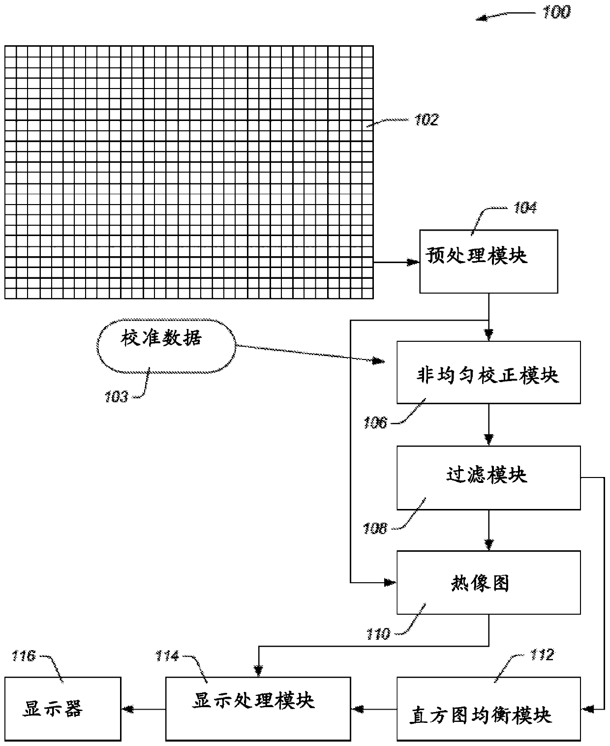
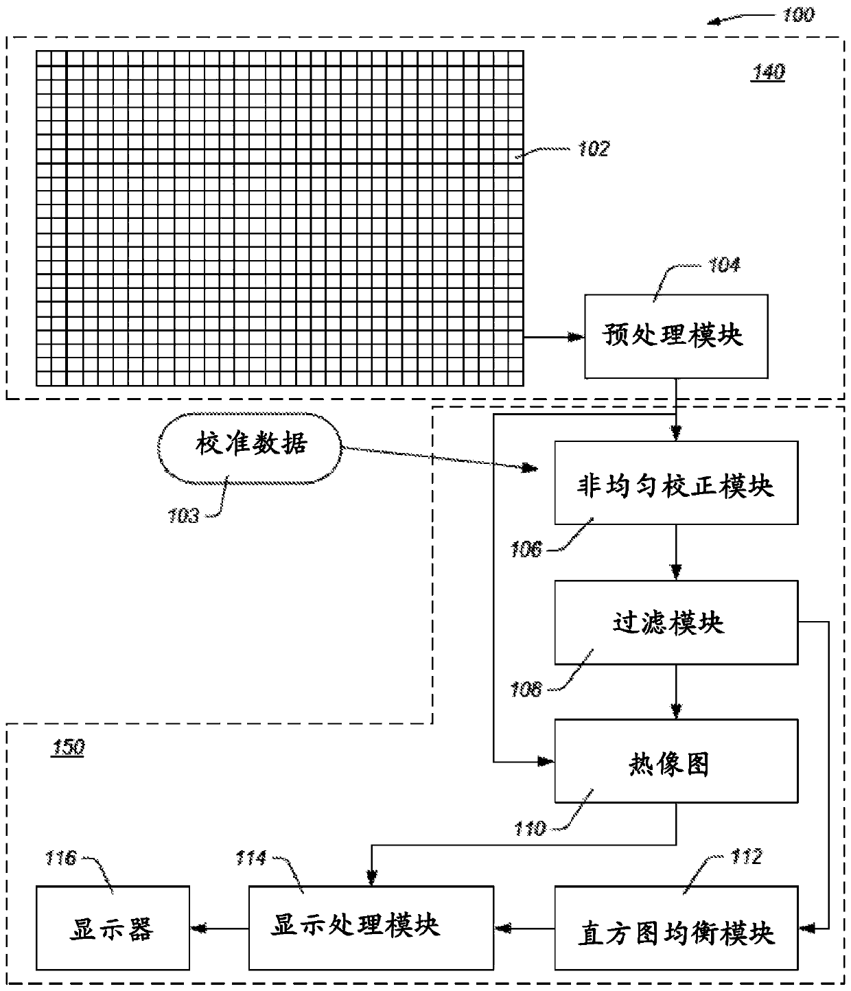
[0025] In general, embodiments of the present disclosure relate to assigning display colors to thermal image intensity data. Some embodiments provide desirable utility for thermal imaging systems in applications where rapid identification of ambient temperature is important. Some embodiments of the present disclosure include systems and methods for improved color display for certain thermal imaging applications.

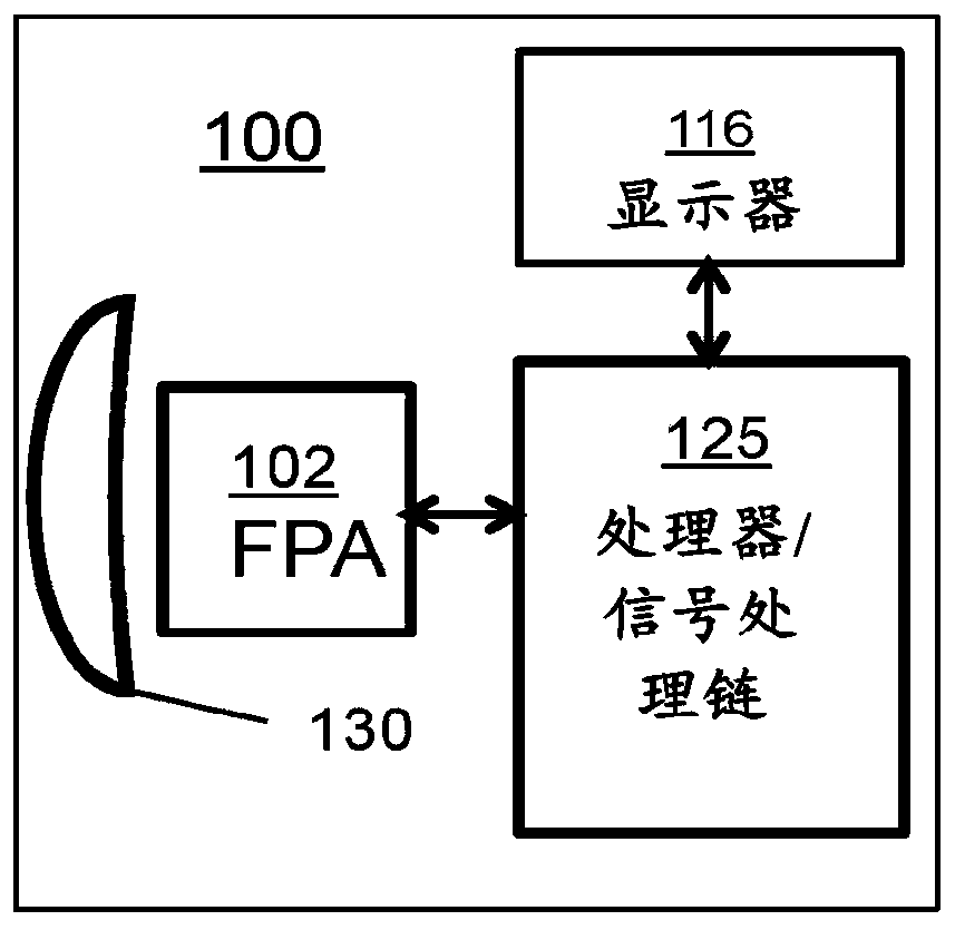
[0026] For purposes of illustration, the examples and implementations described herein focus on imaging systems that include infrared cameras or sensors using focal plane arrays. Aspects of the disclosure will now be described with respect to certain examples and embodiments, which are intended to illustrate rather than limit the disclosure. For many of these aspects, example embodiments will describe an imaging system in which a thermal sensor communicates image data to one or more processors that perform a series of image processing steps, in some implementations ...


PUM


Abstract

Systems and methods for allocating display colors to thermal image intensity data acquired by thermal band photodetectors are described. The intensity data from the photodetectors, which corresponds to the scene temperature, is usually converted to a digital value falling within the range of the analog to digital conversion (ADC). The full ADC range may be divided into two or more sub-ranges. In at least one sub-range intensity values within that sub-range may be assigned display colors from a first color table utilizing one or more Histogram Equalization (HE) techniques. In at least one othersub-range, specific display values from a color table different from the first may be assigned to specific intensity values. In some embodiments, the HE assigned sub-range may be lower in intensity than the specific assigned sub-range. For a thermal imaging system including thermography, the sub-ranges may correspond to scene temperature ranges, where lower temperatures are assigned colors usingHE and higher temperatures are assigned specific colors corresponding to specific temperatures. Such an arrangement is particularly applicable to thermal imaging use by firefighters because the arrangement allows them to determine temperature directly from displayed color for potentially dangerous temperatures. In some cases the sub-range may be applied to certain pixels within desired temperatureranges, and those chosen pixels may be assigned to all or part of a second color table, and in some cases the second color table may be applied to the sub-range pixels by histogram equalization. Thisarrangement is applicable to highlighting temperatures corresponding to objects, such as humans or animals to make these objects high contrast for search applications.

Description

[0001] Cross References to Related Applications [0002] This application claims U.S. Provisional Application No. 62 / 541,550, filed August 4, 2017, entitled "COLOR DISPLAY MODES FOR A THERMAL IMAGING SYSTEM," SYSTEM,” and U.S. Nonprovisional Application No. 16 / 051,077, entitled “COLOR DISPLAY MODES FOR A THERMAL FMAGING SYSTEM,” all of which are hereby incorporated by reference in their entirety. technical field [0003] The present disclosure relates generally to thermal imaging, and in particular to the assignment of display colors to image data. Background technique [0004] The increasing availability of high-performance, low-cost uncooled thermal imaging devices, such as bolometer focal plane array (FPA)-based devices, has enabled the design and production of consumer-oriented thermal imaging capable of high-quality thermal imaging Cameras and sensors. Such thermal imaging systems have long been expensive and difficult to produce, thus limiting the adoption of high-pe...

Claims


Application Information

Patent Timeline
IPC IPC(8): H04N1/46H04N5/33G01J5/02G09G5/02
CPCG01J5/025G01J5/026G01J2005/0077G09G5/02H04N1/465H04N23/23
Inventor R·威廉姆斯R·查欣J·乌尔夫
Owner SEEK THERMAL
Learn More