
Lighting device and window light simulation system

A light-emitting device and simulation system technology, which is applied in the direction of lighting device light guide, lighting device, fixed lighting device, etc., can solve the problem of insufficient simulation and achieve the effect of maintaining transparency and improving taste

Active Publication Date: 2022-02-01
AU OPTRONICS CORP
View PDF7 Cites 0 Cited by
  • Summary
  • Abstract
  • Description
  • Claims
  • Application Information

AI Technical Summary

Problems solved by technology

[0007] In view of the above-mentioned problems in the prior art, the main purpose of the present invention is to provide a light emitting device and a window light simulation system to improve the insufficient simulation of simulated sunlight irradiation.

Method used


Image

  • Lighting device and window light simulation system
  • Lighting device and window light simulation system
  • Lighting device and window light simulation system

Examples


Embodiment Construction

[0076] In order to facilitate the understanding of the technical features, content and advantages of the present invention and the technical effects that can be achieved, the present invention is hereby combined with the accompanying drawings, and is described in detail as follows in the form of embodiments, and the accompanying drawings used herein, its gist It is only for the purpose of illustration and auxiliary description, not necessarily the true proportion and precise configuration of the present invention after implementation, so the attached drawings should not be interpreted based on the proportion and configuration relationship of the attached drawings, and the claims that limit the actual implementation of the present invention are complied with. Explain first.

[0077] In the drawings, the thickness or width of layers, films, panels, regions, light guides, etc., are exaggerated for clarity. Throughout the specification, the same reference numerals denote the same ...


PUM


Abstract

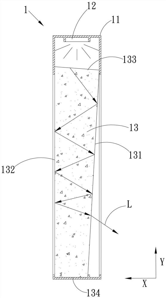
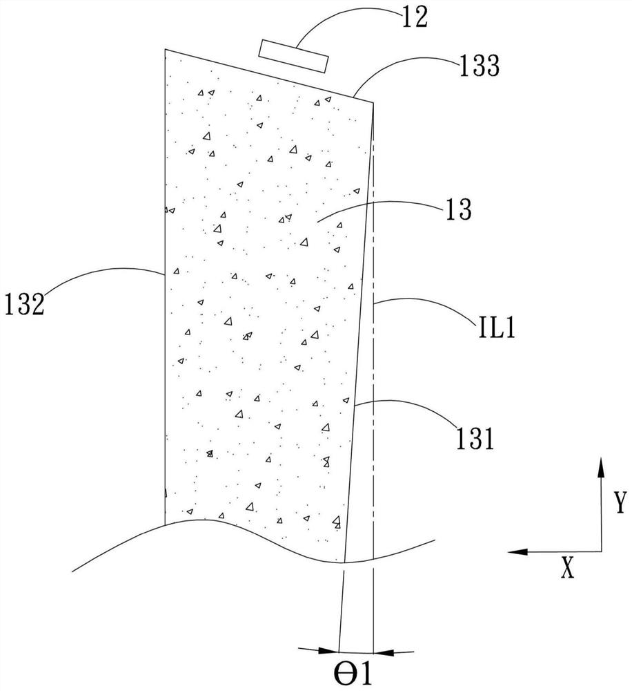
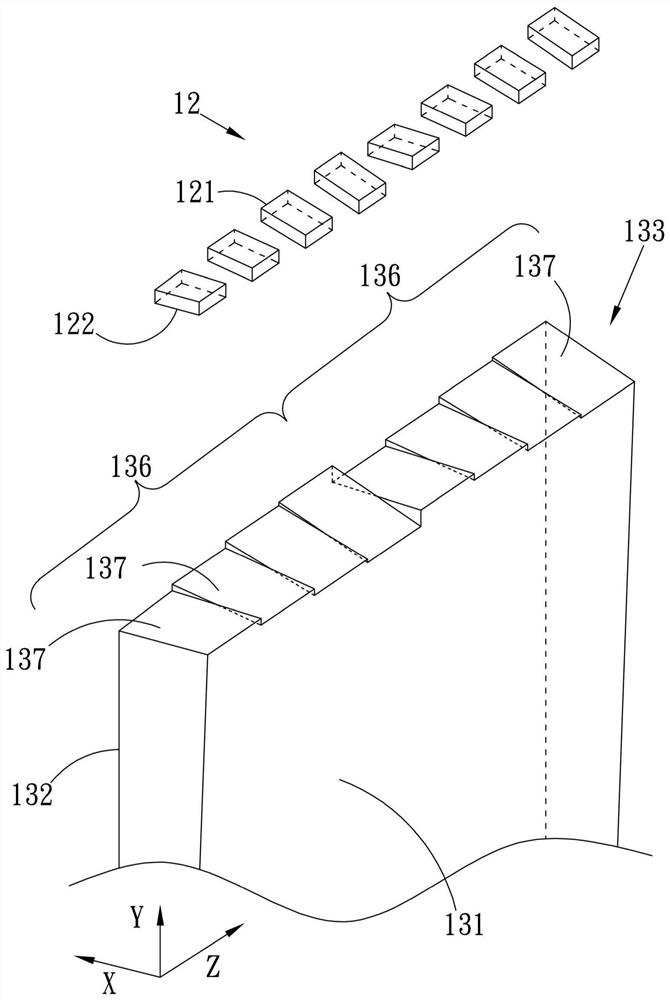
The invention discloses a light emitting device and a window light simulation system. Wherein, the light emitting device includes a fixed frame, a light source module and a light guide. Wherein, the light source module and the light guide are arranged on the fixed frame. The light source module is configured to emit light, and the light guide is located on one side of the light source module; the light guide has a non-parallel first surface, a second surface and a light incident end between the first surface and the second surface. The light incident end is opposite to the light source module to receive light, and the light leaves the light guide at least from the first surface. Wherein, the light incident end has a specific structure for receiving light. Thereby, the present invention can maintain the transparency of the light guide and achieve a good effect of simulating sunlight.

Description

technical field [0001] The invention relates to the technical field of a light emitting device, in particular to a light emitting device capable of simulating sunlight irradiation and a window light simulation system. Background technique [0002] Many buildings and other buildings in the current society will set up many activity spaces on one floor, such as control rooms, meeting rooms and other spaces. However, not each of these activity spaces has windows through which sunlight can directly enter, so that people moving in these activity spaces cannot watch sunlight or outdoor scenery. This situation will affect the mood of people who are active in these activity spaces, or cannot provide a channel for adjusting the body and mind. [0003] Although it is possible to set up a light-emitting device that imitates the irradiation of sunlight, or a display device that can display pictures such as scenery, etc., in these activity spaces to achieve the purpose of providing physi...

Claims


Application Information

Patent Timeline
Patent Type & Authority Patents(China)
IPC IPC(8): F21S8/00F21V19/00F21V8/00F21Y115/10F21Y115/15
CPCF21S8/00F21V19/001F21V2200/00F21Y2115/10F21Y2115/15
Inventor 蔡宗辉
Owner AU OPTRONICS CORP
Learn More