Acoustic resistance material testing device

A testing device and technology for acoustic resistance materials, which are applied in measurement devices, analysis materials, and material analysis using sonic/ultrasonic/infrasonic waves, etc., can solve the problems affecting the efficiency of testing, the complex operation of the testing device for acoustic resistance materials, and the low testing accuracy. and other problems to achieve the effect of improving test efficiency, facilitating re-testing, and improving accuracy

Inactive Publication Date: 2020-05-05
CHANGZHOU INST OF TECH
View PDF0 Cites 4 Cited by
  • Summary
  • Abstract
  • Description
  • Claims
  • Application Information

AI Technical Summary

Problems solved by technology

[0010] The invention solves the problem that the operation of the acoustic resistance material testing device in the related art is relatively complicated, thus affecting the test efficiency and the test accuracy is relatively low, and proposes a sound resistance material testing device, which can improve the testing efficiency and accuracy

Method used


Image

  • Acoustic resistance material testing device
  • Acoustic resistance material testing device
  • Acoustic resistance material testing device

Examples


Embodiment 1

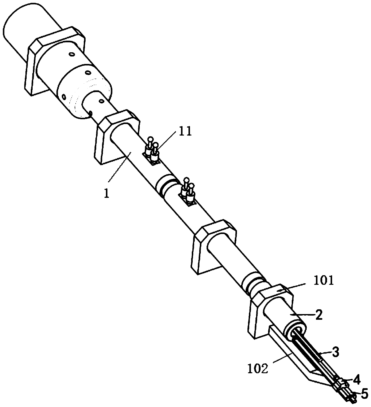
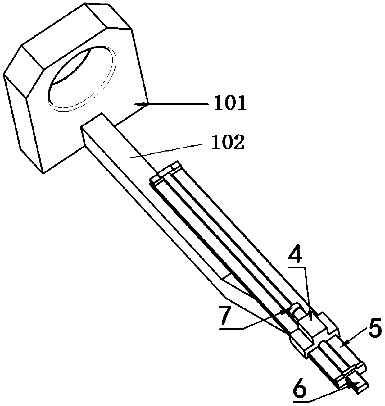
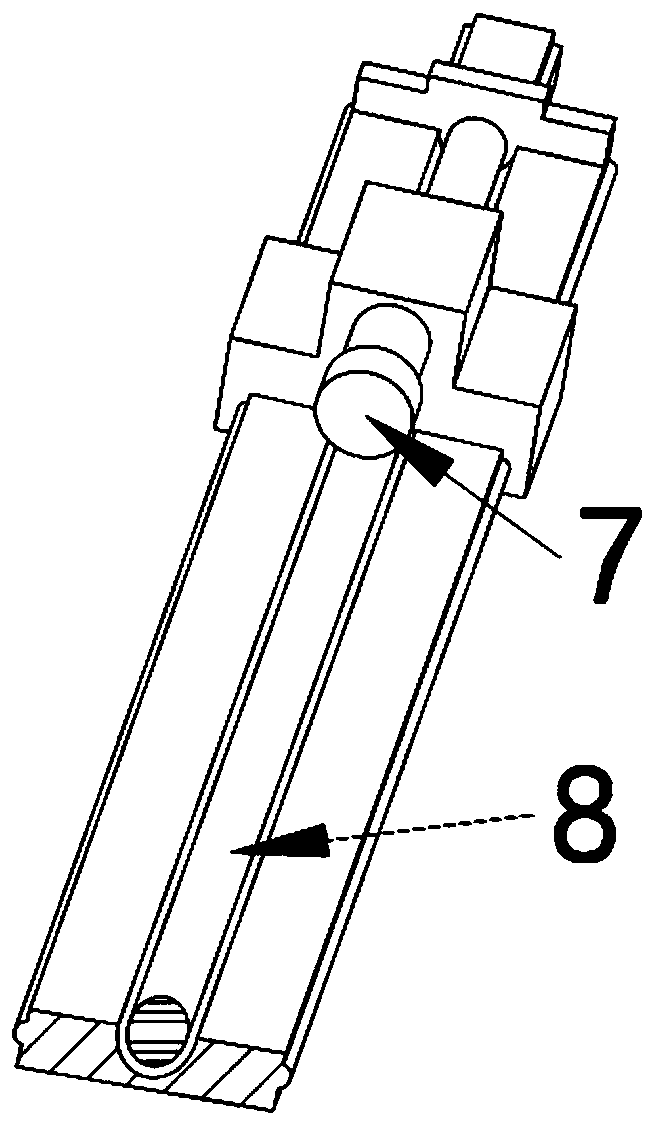
[0046] Such as Figures 1 to 4 And shown in 9, a kind of acoustic resistance material testing device, comprises:

[0047] A plurality of sound resistance tubes, each sound resistance tube can be detachably connected, the sound resistance tube includes the first end sound resistance tube 1 and the end sound resistance tube 2, and the first end sound resistance tube 1 and the end sound resistance tube 2 are equipped with pickups 11;

[0048] A sliding pair, the sliding pair includes a slider 4 and a slide rail 5, and the slide rail 5 is installed on the supporting device through a mounting plate 9 and bolts;

[0049] Feeding device, the feeding device is installed on the slide rail 5 and is used to drive the slider 4 to slide along the slide rail 5;

[0050] The sound-absorbing cotton adjustment slide bar 3, the sound-absorbing cotton adjustment slide bar 2 is installed on the supporting device and located on one side of the slide rail 5; the sound-absorbing cotton adjustment ...

Embodiment 2

[0062] Such as Figures 5 to 9 Shown, a kind of acoustic resistance material testing device comprises:

[0063] A plurality of sound resistance tubes, each sound resistance tube can be detachably connected, the sound resistance tube includes the first end sound resistance tube 1 and the end sound resistance tube 2, and the first end sound resistance tube 1 and the end sound resistance tube 2 are equipped with pickups 11;

[0064] A sliding pair, the sliding pair includes a slider 4 and a slide rail 5, and the slide rail 5 is installed on the supporting device through a mounting plate 9 and bolts;

[0065] Feeding device, the feeding device is installed on the slide rail 5 and is used to drive the slider 4 to slide along the slide rail 5;

[0066] The sound-absorbing cotton adjustment slide bar 3, the sound-absorbing cotton adjustment slide bar 3 is installed on the supporting device and located on one side of the slide rail 5; the sound-absorbing cotton adjustment slide bar ...


PUM


Abstract

The invention relates to the technical field of acoustic resistance material testing, in particular to an acoustic resistance material testing device which comprises a plurality of acoustic resistancetubes, a sliding pair, a feeding device, an acoustic absorption cotton adjusting sliding rod and a fine adjusting bolt. The acoustic resistance tubes comprise a head end acoustic resistance tube anda tail end acoustic resistance tube; the sliding pair comprises a sliding block and a sliding rail, and the sliding rail is installed on a supporting device through an installation plate and bolts. The feeding device is mounted on the sliding rail; the tail end acoustic resistance tube is installed on the supporting device and located on one side of the sliding rail. The sound absorption cotton adjusting sliding rod is installed in the tail end acoustic resistance tube and provided with a scaleplate. The fine adjusting bolt is connected into the counter bore of the sliding block in a screwed mode and located on the side close to the sound absorption cotton adjusting sliding rod, and the fine adjusting bolt and the sound absorption cotton adjusting sliding rod are coaxial. Linear feeding isachieved through the feeding device, motion can be directly transmitted, no transfer device is needed, reverse motion is avoided, testing steps are simplified and the accuracy of testing results is improved.

Description

technical field [0001] The invention relates to the technical field of acoustic resistance material testing, in particular to an acoustic resistance material testing device. Background technique [0002] The acoustic resistance material tester is an instrument used to test the acoustic properties of materials, and plays an important role in the analysis of acoustic materials. Acoustic material testing can be used to characterize material-related uses, obtain specific material properties, test and evaluate manufacturing quality, and this information can be used for teaching. [0003] Acoustic material testing can determine material properties by exposing test pieces to production and measuring their effect on production. Different needs and test conditions require different methods to measure. For this reason, corresponding test conditions and specific equipment have been developed according to national standards to ensure high repeatability and reproducibility. [0004] T...

Claims


Application Information

Patent Timeline
Patent Type & Authority Applications(China)
IPC IPC(8): G01N29/04G01N29/09G01N29/22G01N29/26
CPCG01N29/04G01N29/09G01N29/22G01N29/26
Inventor 孙文许方贤张建梅孙功畅王振源罗洋朱虹国
Owner CHANGZHOU INST OF TECH
Why Eureka
Try Eureka