Indoor testing device and method for solidified residual soil by virtue of microorganism grouting technique

An indoor test and residual soil technology, which is used in soil material testing, material inspection products, preparation of test samples, etc., can solve the problems of unevenness, insufficient precision, waste of resources, etc. The effect of saving resources

Pending Publication Date: 2017-11-17
FUZHOU UNIV
View PDF10 Cites 10 Cited by
  • Summary
  • Abstract
  • Description
  • Claims
  • Application Information

AI Technical Summary

Problems solved by technology

Because the cemented body sample prepared by this method is difficult to take out directly from the mold, it is usually necessary to cut the mold before performing subsequent tests on the cemented body, which increases the difficulty of testing and evaluation, and cutting may also cause certain damage to the cemented body itself. The damage will cause certain errors to the follow-up test results; moreover, due to the insufficient precision of the material production itself, the inner diameter is not uniform enough, and does not meet the standard compression test requirements, the prepared cemented body itself may There will be inhomogeneity, which will directly cause errors in the follow-up test results.
Moreover, due to the one-time use of plastic molds, after a sample is prepared, it can only be discarded directly after cutting, which causes a certain waste of resources. At the same time, the characteristics of plastics may also cause certain pollution to the environment.
In addition, this type of grouting method has a low utilization rate of the bacterial solution, generally no more than 65% of the injected bacterial solution, and most of the outflowed bacterial solution is directly discarded, and there is also a large waste of resources

Method used


Image

  • Indoor testing device and method for solidified residual soil by virtue of microorganism grouting technique
  • Indoor testing device and method for solidified residual soil by virtue of microorganism grouting technique
  • Indoor testing device and method for solidified residual soil by virtue of microorganism grouting technique

Examples


Embodiment Construction

[0027] Below in conjunction with embodiment the method of the present invention is described in further detail. It should be noted that the protection scope of the present invention shall include but not be limited to the technical content disclosed in this embodiment.

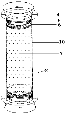
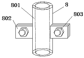
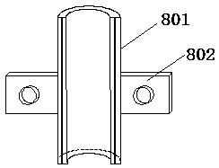
[0028] The indoor test device for the microbial grouting technology of the present invention to consolidate residual soil comprises an iron stand 14 and a stainless steel split mold 8 clamped and fixed on the iron stand, wherein the stainless steel split mold 8 is filled with residual soil particles 7, and the stainless steel split mold 8 A coarse sand cushion 6 and a gauze cushion 5 are arranged in the split mold 8 above and below the residual soil particles, and the stainless steel split mold ports are respectively plugged with an upper single-hole rubber plug 4 and a lower single-hole rubber plug 15 , the lower single-hole rubber plug penetrates the lower drainage tube 11, the lower drainage tube is provide...


PUM


Abstract

The invention relates to an indoor testing device and method for solidified residual soil by virtue of a microorganism grouting technique. The device is characterized by comprising an iron stand frame and a stainless steel splitting mold fixedly clamped on the iron stand frame, wherein the stainless steel splitting mold is filled with residual soil particles, a coarse sand pad layer and a gauze pad layer are sequentially arranged on and under the residual soil particles in the stainless steel splitting mold, ports of the stainless steel splitting mold are respectively plugged with an upper single-hole rubber plug and a lower single-hole rubber plug, a lower drainage tube penetrates into the lower single-hole rubber plug, a water stop clamp is arranged on the lower drainage tube, the upper single-hole rubber plug is sequentially connected with a flow guide pipe and a liquid storage device, and a peristaltic pump is connected to a middle section of the flow guide pipe. The indoor testing device is simple in structure and reasonable in design, resources are saved, and the difference between experiment data and actual soil property is reduced.

Description

Technical field: [0001] The invention relates to an indoor test device and test method for residual soil consolidated by microbial grouting technology. Background technique: [0002] With the gradual increase in the requirements for sustainable development worldwide, the development of green environmental protection engineering technology is also growing. The use of microbially induced calcium carbonate deposition (MICP) technology for the strengthening of sandy soft soil layers is a new grouting technology in recent years. This method mainly uses the mineralization of specific mineralizing bacteria to strengthen the mechanical properties of sandy soil. It is innovative in theory and technology, and has the advantages of small grouting pressure, large grouting range, and no pollution, which will have a profound impact on the protection of the ecological environment. [0003] The rise of MICP technology has been going on for more than 20 years. However, the medium used in ...

Claims


Application Information

Patent Timeline
Patent Type & Authority Applications(China)
IPC IPC(8): G01N1/36G01N33/24
CPCG01N1/36G01N33/24
Inventor 黄明靳贵晓邱继业
Owner FUZHOU UNIV
Why Eureka
Try Eureka