
Modular fine-grained synchronous design method and system for mold

A design method and fine-grained technology, applied in the field of mold modular fine-grained synchronous design method and system, can solve problems such as reducing the dependence of technicians on experience data loss, division of overall product tasks, and inability to meet mold companies' rapid response to market demand, etc. , to achieve the effect of reducing the degree of dependence, improving design efficiency and design quality

Active Publication Date: 2020-05-05
HUAZHONG UNIV OF SCI & TECH
View PDF3 Cites 2 Cited by
  • Summary
  • Abstract
  • Description
  • Claims
  • Application Information

AI Technical Summary

Problems solved by technology

However, when designing molds in existing design methods, a design expert is required to complete all design tasks from beginning to end. In addition, similar molds or structures still need to be redesigned, resulting in long design cycles and successful design schemes. Mold companies quickly respond to new requirements of market demand
At the same time, in the existing technology, when assigning design tasks, the whole product is regarded as a design task module, and the overall tasks of the product are not divided according to the characteristics of the product, so that the design resources matched by the design experts are relatively large. error
[0004] In view of the above defects or improvement needs of the existing technology, it is urgent to propose a mold modular fine-grained synchronous design method in this field, which can realize the reuse of design experience or knowledge, and minimize the dependence on technicians and technicians. Flow brings risk of loss of experience data

Method used


Image

  • Modular fine-grained synchronous design method and system for mold
  • Modular fine-grained synchronous design method and system for mold
  • Modular fine-grained synchronous design method and system for mold

Examples


Embodiment Construction

[0057] In order to make the object, technical solution and advantages of the present invention clearer, the present invention will be further described in detail below in conjunction with the accompanying drawings and embodiments. It should be understood that the specific embodiments described here are only used to explain the present invention, not to limit the present invention. In addition, the technical features involved in the various embodiments of the present invention described below can be combined with each other as long as they do not constitute a conflict with each other.

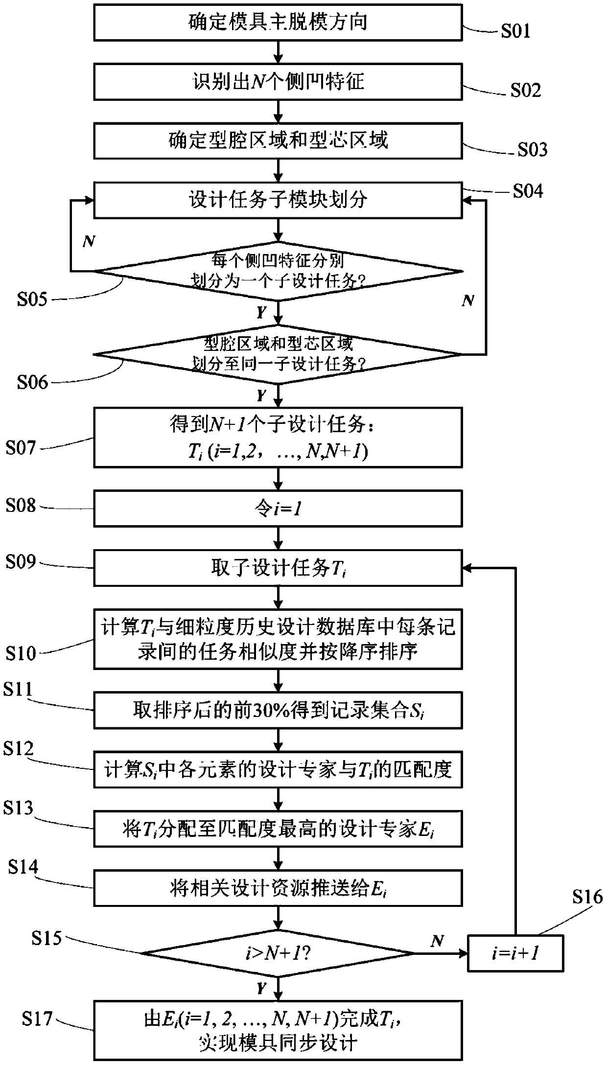
[0058] Such as figure 1 As shown, a mold modular fine-grained synchronous design method includes the following steps:

[0059] S01. Determine the main demoulding direction of the mold, and jump to S02;

[0060] Specifically, when designing a new mold, the oriented bounding box of the product model is established, and the surface with the largest area in the oriented bounding box is obtained, a...


PUM


Abstract

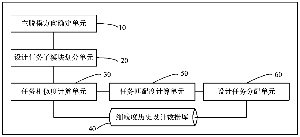
The invention belongs to the field of mold design and manufacturing, and particularly discloses a modular fine-grained synchronous design method and system for a mold. The method comprises the following steps of: determining a primary de-molding direction, recognizing N lateral concave features, a cavity area and a core area of the product model in the main demolding direction of the mold; and dividing sub-design task modules according to the N lateral concave features, the cavity area and the core area, allocating a design expert with the highest comprehensive matching degree to each sub-design task from a fine-grained historical design database, and pushing related design resources, thereby realizing modular fine-grained synchronous design of the mold. The system comprises a main demoulding direction determination unit, a design task submodule division unit, a task similarity calculation unit, a fine-grained historical design database, a task matching degree calculation unit and a design task allocation unit. According to the method and system, the design efficiency and the design quality are improved, and the degree of dependence on technicians and the risk of experience data loss caused by technician movement are reduced.

Description

technical field [0001] The invention belongs to the field of mold design and manufacture, and more specifically relates to a mold modular fine-grained synchronous design method and system. Background technique [0002] Mold is an important basic process equipment in the manufacturing industry, which can have an economic amplification effect of 1:100 on downstream industries. Under the background of market globalization, shortening delivery time and quickly responding to market demand has become the first element for mold companies to participate in market competition. [0003] Mold design is the initial stage of mold manufacturing, which affects the delivery time, quality and cost of the mold. However, when designing molds in existing design methods, a design expert is required to complete all design tasks from beginning to end. In addition, similar molds or structures still need to be redesigned, resulting in long design cycles and successful design schemes. Mold companie...

Claims


Application Information

Patent Timeline
IPC IPC(8): G06F30/17G06Q10/06G06Q10/10G06Q50/04
CPCG06Q10/063112G06Q10/101G06Q50/04Y02P90/30
Inventor 侯斌魁黄志高周华民王云明张云
Owner HUAZHONG UNIV OF SCI & TECH
Learn More