High-performance heat-dissipation waterproof and dustproof electrical cabinet

A waterproof, dustproof, high-performance technology, applied in the field of electrical cabinets, can solve the problems of poor flexibility, low heat dissipation efficiency, rain or dust ingress, etc., to reduce the difficulty of maintenance work, prolong the service life, and improve the effect of heat dissipation

Inactive Publication Date: 2020-05-05
NANNING UNIV
View PDF5 Cites 1 Cited by
  • Summary
  • Abstract
  • Description
  • Claims
  • Application Information

AI Technical Summary

Problems solved by technology

The application of electrical cabinets is very extensive. However, when the electrical cabinets are running, the internal electrical components will emit a large amount of heat. If the heat is not discharged in time, it will cause a huge safety hazard to the safe operation of the electrical cabinets. Existing Conventional electrical cabinets generally have defects such as single function, poor flexibility, and low heat dissipation efficiency. Existing electrical cabinets are generally provided with heat dissipation holes only on one side of the surface, that is, heat can only be dissipated in one direction, and the heat dissipation efficiency is low. And it does not have the function of rainproof, so it is easy for rainwater or dust to enter the electrical cabinet, which will greatly affect the normal operation of the electrical components inside the electrical cabinet

Method used


Image

  • High-performance heat-dissipation waterproof and dustproof electrical cabinet
  • High-performance heat-dissipation waterproof and dustproof electrical cabinet
  • High-performance heat-dissipation waterproof and dustproof electrical cabinet

Examples


Embodiment Construction

[0018] The technical scheme of the present invention will be further described below in conjunction with the accompanying drawings, but the required protection scope is not limited to the description;

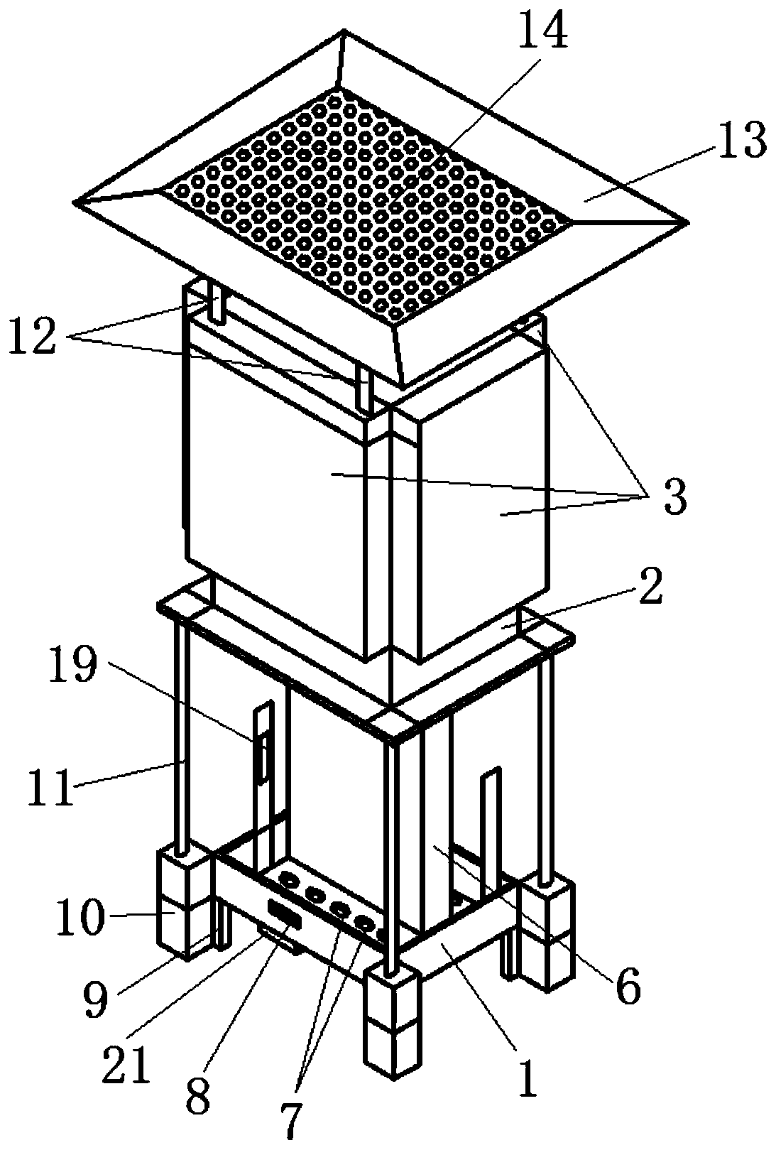
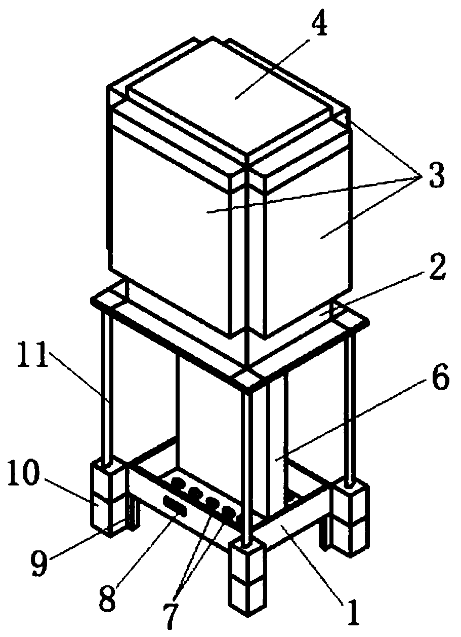
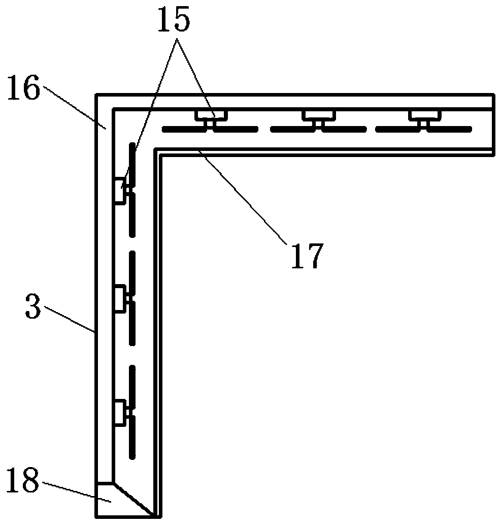
[0019] The invention provides a high-performance heat dissipation, waterproof and dustproof electrical cabinet, such as figure 1 , figure 2 with image 3 As shown, it includes a cabinet body 1, a hydraulic cylinder 11 is installed on the cabinet body 1, an outer cover 2 is fixedly connected to the piston rod of the hydraulic cylinder 11, and a cooling bellows 3 is installed around the outer cover 2, and several cooling fans are installed inside the cooling bellows 3 15. The top of the outer cover 2 is also fixedly connected with a rainshield 13 through the push rod 12, the top surface of the rainshield 13 is equipped with a solar panel 14, and the battery 4 is also installed inside the outer cover 2, and the solar panel 14, the battery 4 and the cooling fan 15 are sequentiall...


PUM


Abstract

The invention relates to a high-performance heat dissipation waterproof and dustproof electrical cabinet. The cabinet comprises a cabinet body. A hydraulic cylinder is mounted on the cabinet body. Anouter cover is fixedly connected with a piston rod of the hydraulic cylinder. Heat dissipation air bellows are installed on the periphery of the outer cover. A plurality of heat dissipation fans are installed in the heat dissipation air bellows. The top of the outer cover is further fixedly connected with a rain baffle through an ejector rod. A solar panel is installed on the top face of the rainbaffle. A storage battery is further installed in the outer cover, and the solar panel, the storage battery and the heat dissipation fans are electrically connected in sequence. According to the technical scheme of the invention, heat energy generated during operation of electrical elements can be dissipated in multiple directions around the outer cover; heat dissipation capability is effectivelyimproved; the rainproof effect on the electrical cabinet is achieved through the rain baffle. the electrical elements in the electrical cabinet are effectively protected; the outer cover can be jacked up through the hydraulic cylinder, and thus maintenance personnel can conveniently carry out maintenance work on the interior of the electrical cabinet; solar energy is absorbed through the solar panel to supply power to the electrical elements in the electrical cabinet; and the service life of equipment is prolonged.

Description

technical field [0001] The invention belongs to the technical field of electric cabinets, in particular to a high-performance heat dissipation, waterproof and dustproof electric cabinet. Background technique [0002] The electrical cabinet is a cabinet made of steel to protect the normal operation of components. The materials for making electrical cabinets are generally divided into two types: hot-rolled steel plates and cold-rolled steel plates. Compared with hot-rolled steel sheets, cold-rolled steel sheets are softer and more suitable for the production of electrical cabinets. Electrical cabinets are widely used mainly in chemical industry, environmental protection industry, power system, metallurgical system industry, nuclear power industry, fire safety monitoring, transportation industry and so on. The application of electrical cabinets is very extensive. However, when the electrical cabinets are running, the internal electrical components will emit a large amount of ...

Claims


Application Information

Patent Timeline
Patent Type & Authority Applications(China)
IPC IPC(8): H02B1/56H02B1/30H02B1/28
CPCH02B1/28H02B1/30H02B1/565
Inventor 梁承权
Owner NANNING UNIV
Why Eureka
Try Eureka