
Waterproof and breathable structure of starter

A waterproof, breathable and starter technology, applied in the direction of electrical components, electromechanical devices, electric components, etc., can solve the problems of increasing the overall cost, low applicability, increasing structural complexity, etc., to ensure stable operation, convenient installation, and structural simple effect

Pending Publication Date: 2020-05-05
WUXI MINGCHENG AUTOMOBILE PARTS CO LTD
View PDF0 Cites 0 Cited by
  • Summary
  • Abstract
  • Description
  • Claims
  • Application Information

AI Technical Summary

Problems solved by technology

In this regard, at present, the air pressure balance in the inner cavity is achieved by setting the valve body structure of

Method used


Image

  • Waterproof and breathable structure of starter
  • Waterproof and breathable structure of starter
  • Waterproof and breathable structure of starter

Examples


Embodiment 1

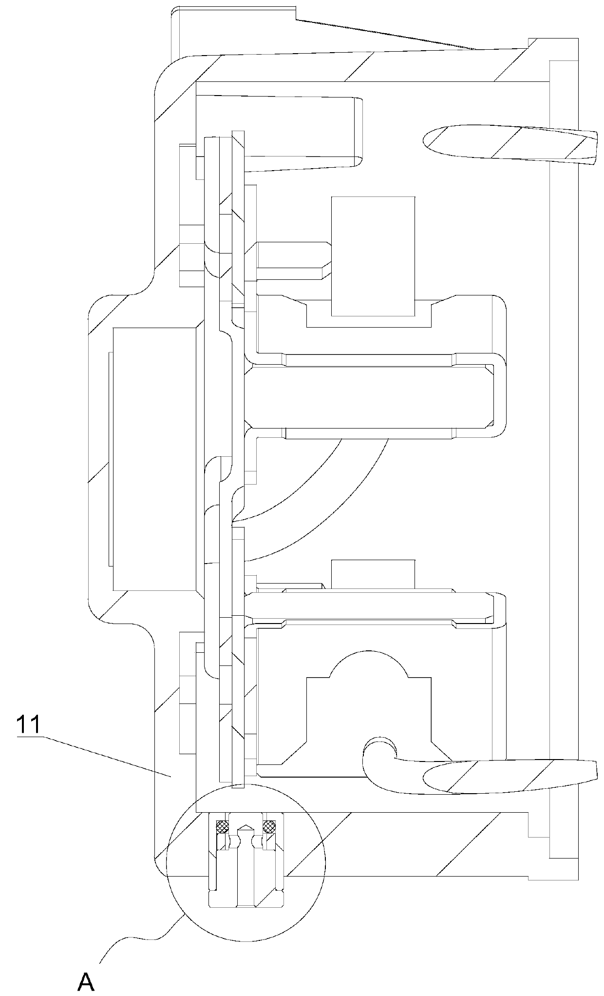
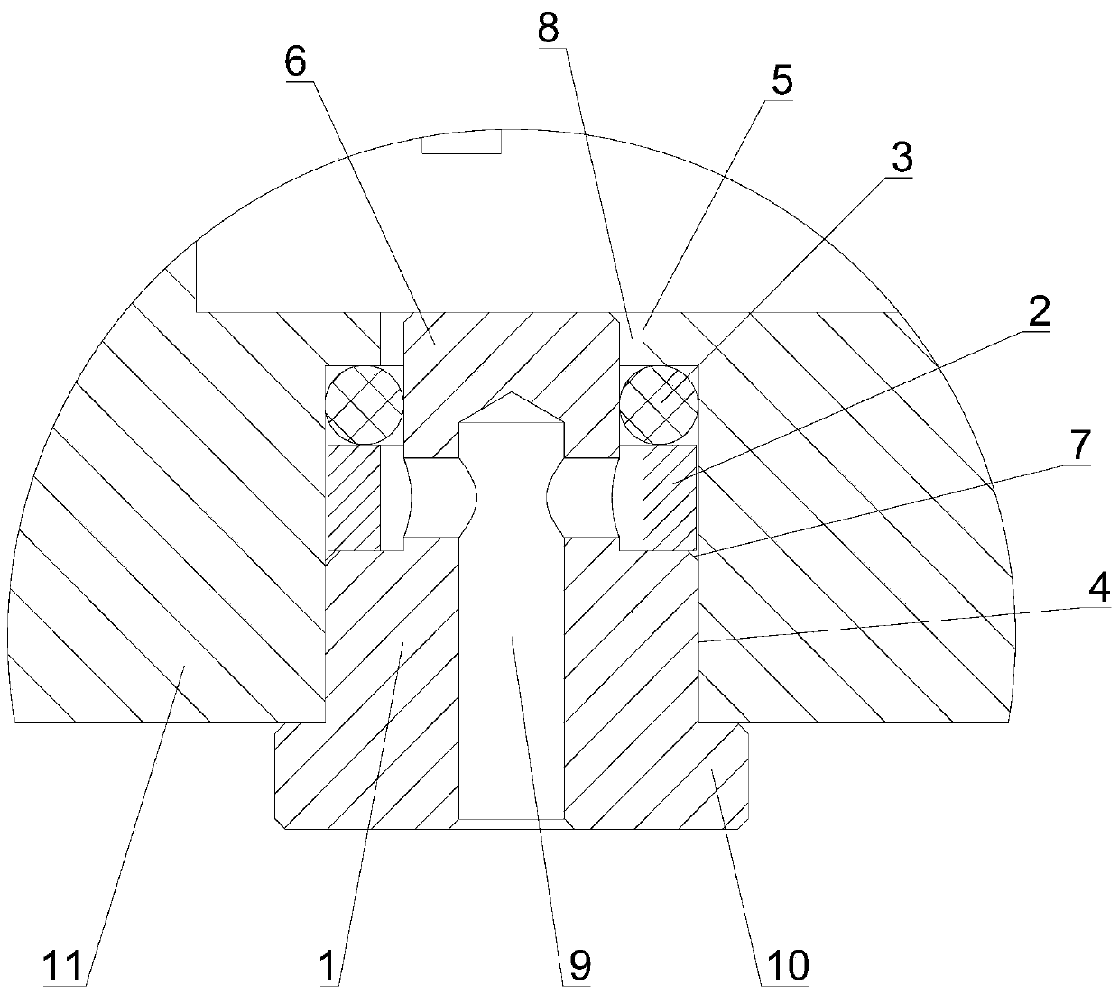
[0020] see figure 1 and 2 As shown, this embodiment provides a starter waterproof and breathable structure, which is arranged on the starter casing and can be installed at any suitable position on the starter casing as required. In this embodiment, the waterproof seal is set on the starter rear cover structure as an example.

[0021] The waterproof and breathable structure includes a breathable seat 1 , a bush 2 and a rubber sealing ring 3 .

[0022] The rear cover shell 11 is provided with an installation cavity 4 extending inward from the outer wall, and a through hole 5 is provided on the end wall of the installation cavity 4 to communicate the inner cavity with the outside.

[0023] The air-permeable seat 1 includes a main body and a plug 6. The plug 6 is arranged at the front end of the main body and forms a limit step 7. The main body is sealed and assembled with the installation cavity 4. Specifically, the main body and the installation cavity 4 are fitted through thr...

Embodiment 2

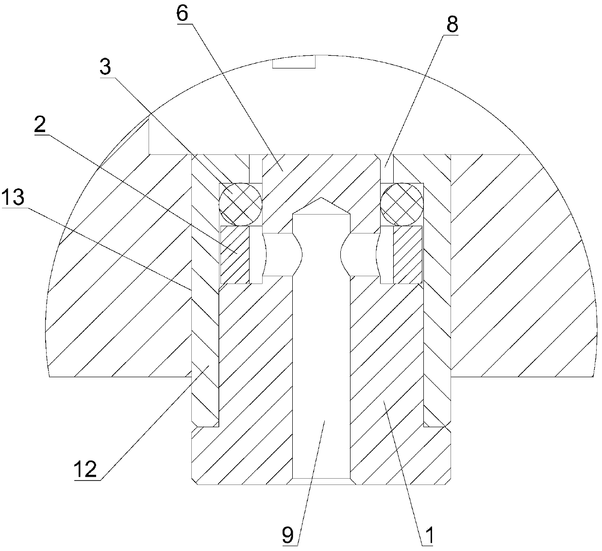
[0028] see image 3 As shown, this embodiment provides a starter waterproof and breathable structure. Under the inspiration of Embodiment 1, the waterproof and breathable structure also includes a mounting seat 12. In order to reduce the processing difficulty of the starter shell, only the Open the assembly hole 13 at the required position, form the installation cavity 4 on the installation seat 12, and then set the breathable seat 1, the bushing 2 and the rubber sealing ring 3, and finally fit the thread or interference fit between the installation seat 12 and the assembly hole 13 , to ensure tightness.

[0029] In summary, the waterproof and breathable structure of the starter cooperates with the breather seat through the sealing ring, and utilizes the principle of elastic deformation of the rubber body to realize the functions of liquid barrier and gas passage in the breather channel. The structure is simple, the cost is low, and the setting is convenient. It can be install...


PUM


Abstract

The invention discloses a waterproof and breathable structure of a starter. The structure is arranged on a starter housing, and comprises a ventilation seat, a bushing and a rubber sealing ring. A mounting cavity is formed in the starter housing. A through hole is formed in the end surface wall of the mounting cavity. The ventilation seat comprises a main body part and a plug. The plug is arrangedat the front end of the main body part and forms a limiting step. The main body part and the mounting cavity are hermetically assembled. The plug extends into the through hole, and a ventilation seamis reserved between the plug and the through hole. Vent holes are formed in the ventilation seat. The vent holes are communicated with the ventilation seam to form a ventilation channel. The bushingis sleeved on the plug in a clearance manner and is limited by the limiting step. The rubber sealing ring is arranged in a space defined by the bushing, the end face wall of the mounting cavity and the plug. The rubber sealing ring is attached to the surfaces of the bushing, the mounting cavity and the plug at the same time to block liquid in the ventilation channel. When the air pressure difference exists between the two sides of the rubber sealing ring, the rubber sealing ring generates elastic deformation to form an air gap allowing air to pass through.

Description

technical field [0001] The invention relates to the technical field of motor sealing, in particular to a waterproof and breathable structure of a starter. Background technique [0002] The inner cavity of the motor is generally a closed or high-seal structure to improve the protection of the inner cavity, especially in harsh environmental conditions, which require higher sealing. However, the motor will generate heat when it is continuously working. The inner cavity is sealed, which causes the internal gas to expand, the internal pressure rises and the body ruptures, and even under extreme conditions, the high temperature heat causes the motor to burn out. In order to avoid the above situation, it is necessary to design a ventilating structure for the motor, so as to adjust the pressure in its inner cavity, but it is necessary to ensure its waterproof and sealing performance. In this regard, at present, the air pressure balance in the inner cavity is realized by setting a v...

Claims


Application Information

Patent Timeline
IPC IPC(8): H02K5/04H02K5/10
CPCH02K5/04H02K5/10H02K2205/09
Inventor 曹向明
Owner WUXI MINGCHENG AUTOMOBILE PARTS CO LTD
Learn More