Supercharge Your Innovation With Domain-Expert AI Agents!

A method for assembling the stator and rotor shafts of a motor

A stator-rotor and shaft assembly technology, which is applied in the direction of centering/balancing the rotor, etc., can solve the problems of difficult measurement accuracy, difficult test operation space, uneven stator-rotor air gap, etc., to improve the installation coaxiality and improve the performance of the motor , Improve the effect of operating performance

Active Publication Date: 2021-04-30
WUHAN MARINE ELECTRIC PROPULSION RES INST CHINA SHIPBUILDING IND CORP NO 712 INST
View PDF12 Cites 0 Cited by
  • Summary
  • Abstract
  • Description
  • Claims
  • Application Information

AI Technical Summary

Problems solved by technology

[0004] Among the above two methods, the former involves accumulating multiple processing and assembly errors, the coaxiality of the stator and rotor is completely guaranteed by processing, and there is no actual measurement data for the actual coaxial effect between the stator and rotor, resulting in doubts about the consistency of the coaxial effect of the stator and rotor, and In large-sized motors, it is difficult to effectively guarantee the coaxiality between the stacked iron core and the notch of the machine base, and its coaxial effect cannot be guaranteed; although the latter relies on the actual measurement of the rotor air gap to adjust the bearing position, the actual operation process On the one hand, the air gap between the stator and the rotor is not uniform, so it is difficult to measure accurately. On the other hand, due to the difficulty in the test operation space, especially for permanent magnet motors with pressure plates or fans installed at both ends, it is difficult to effectively and accurately test the gap between the stator and rotor. The air gap between the stator and the rotor makes it difficult to guarantee the coaxiality accuracy between the stator and the rotor

Method used


Image

  • A method for assembling the stator and rotor shafts of a motor
  • A method for assembling the stator and rotor shafts of a motor

Examples


Embodiment Construction

[0022] The specific embodiments of the present invention will be further described below in conjunction with the accompanying drawings.

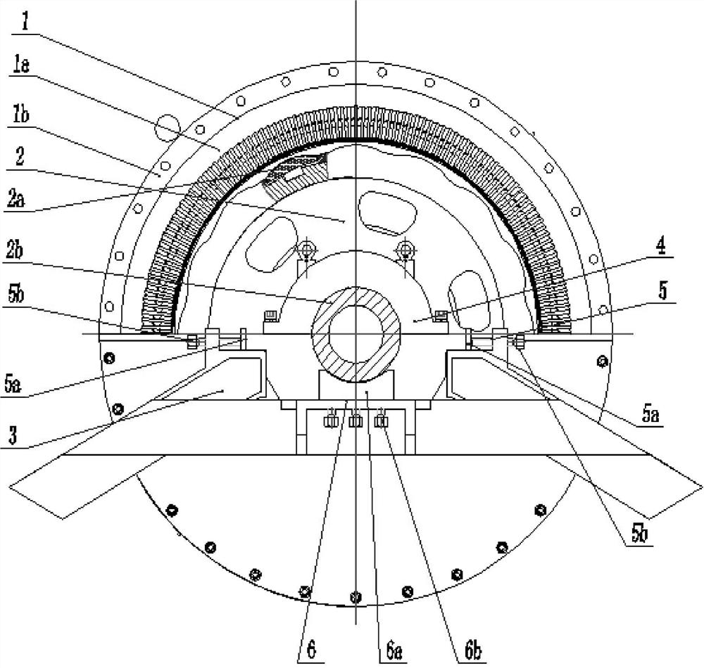
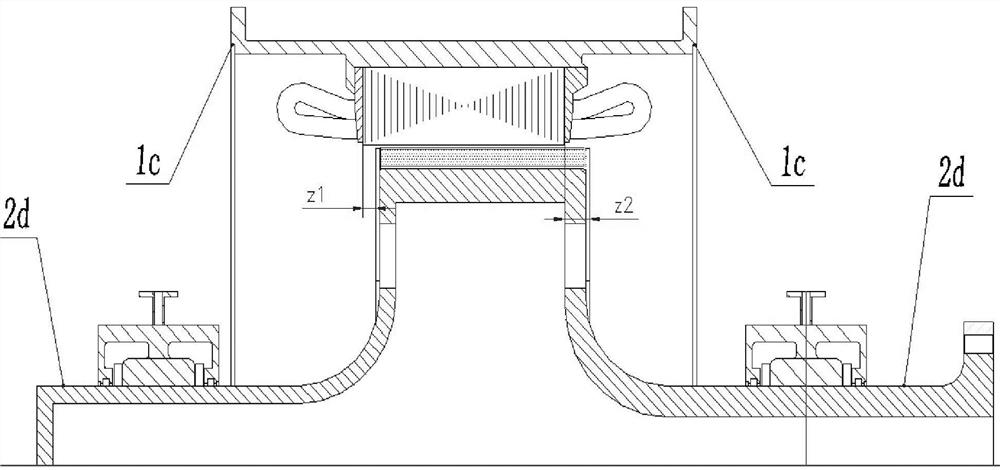
[0023] refer to figure 1 and figure 2 As shown, the invention discloses a method for assembling the stator and rotor shafts of a motor. When the stator core 1a is assembled in the stator frame 1b, the inner circle of the stator core 1a is used as a reference, and the characteristic stops are processed at both ends of the stator frame 1b in advance. The coaxiality of the mouth 1c, the characteristic seam 1c and the inner circle of the stator core 1a is determined according to the design requirements.

[0024] The assembly object of this patent is composed of a stator assembly 1, a rotor assembly 2, an end cover 3 and a bearing assembly 4. The stator assembly 1 is composed of a stator core 1a and a stator frame 1b, and the rotor assembly 2 is composed of a rotor core 2a , the rotating shaft 2b, the rotor end plate 2c and the rotating shaft ...


PUM


Abstract

The invention discloses a motor stator-rotor alignment shaft assembly method. Based on a motor composed of a stator assembly, a rotor assembly, an end cover and a bearing assembly, the two ends of the stator frame of the stator assembly are processed in advance for detection. The spigot is processed based on the actual stator core (axis center), and its coaxiality is determined according to the design requirements. The shaft extension at both ends of the rotor assembly and the bearing gear have the coaxiality requirements. Taking the characteristic notches at both ends of the frame as the benchmark, use high-precision three-coordinate measuring tools to detect the coaxiality between the characteristic notch and the rotor shaft extension on the corresponding side, and use the end cover bearing to fine-tune the components and external tooling, respectively for X, Adjust the position of the rotor assembly in the Y and Z directions to achieve the purpose of improving the installation coaxiality between the stator and the rotor.

Description

technical field [0001] The invention belongs to the technical field of electric motors, and relates to a shaft-aligning assembly method of a stator and a rotor of a motor, which is suitable for the detection of the coaxiality of the stator and the rotor in the general assembly process of the motor and the application of centering for installing bearings. Background technique [0002] The installation of the coaxiality between the stator and the rotor of the motor is one of the key factors to ensure the performance of the motor. A technical difficulty in stator and rotor installation, especially for high-power permanent magnet motors. [0003] In the traditional motor production, the common methods of positioning and installation between the stator and rotor are: through the proper fit between the iron core and the machine base, the coaxiality between the inner circle of the machine base and the seam of the machine base, the seam of the end cover and the seam of the machine b...

Claims


Application Information

Patent Timeline
Patent Type & Authority Patents(China)
IPC IPC(8): H02K15/16
CPCH02K15/16
Inventor 吕长朋张立春
Owner WUHAN MARINE ELECTRIC PROPULSION RES INST CHINA SHIPBUILDING IND CORP NO 712 INST
Features
  • R&D
  • Intellectual Property
  • Life Sciences
  • Materials
  • Tech Scout
  • Unparalleled Data Quality
  • Higher Quality Content
  • 60% Fewer Hallucinations
Learn More