Clamping device for bearing ring cutting machining

A technology of cutting processing and clamping device, applied in the field of mechanical processing, can solve problems such as wasting time, increasing power consumption, and difficult clamping

Pending Publication Date: 2020-05-08
常州市大华环宇机械制造有限公司
View PDF0 Cites 8 Cited by
  • Summary
  • Abstract
  • Description
  • Claims
  • Application Information

AI Technical Summary

Problems solved by technology

The bearing ring has a cylindrical structure and is not easy to be clamped during cutting. At the same time, the existing clamping device for cutting can only clamp one bearing ring at a time. After the cutting is completed, it needs to pause and then clamp a new one. The bearing ring, which undoubtedly wastes time and increases power consumption, needs to be improved urgently

Method used


Image

  • Clamping device for bearing ring cutting machining
  • Clamping device for bearing ring cutting machining
  • Clamping device for bearing ring cutting machining

Examples


Embodiment Construction

[0019] The following will clearly and completely describe the technical solutions in the embodiments of the present invention with reference to the accompanying drawings in the embodiments of the present invention. Obviously, the described embodiments are only some, not all, embodiments of the present invention. Based on the embodiments of the present invention, all other embodiments obtained by persons of ordinary skill in the art without making creative efforts belong to the protection scope of the present invention.

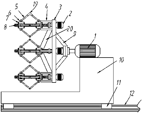
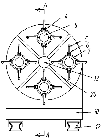
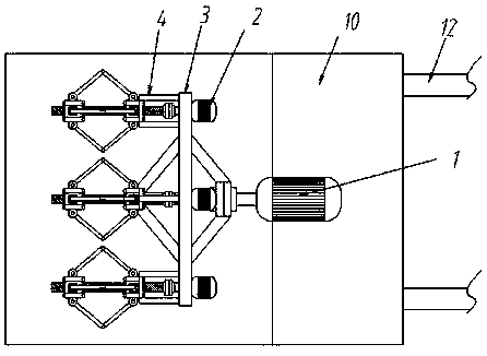
[0020] Such as Figure 1-Figure 4 As shown, this specific embodiment adopts the following technical scheme: it includes motor No. 1, motor No. Slider 11, slide rail 12, main shaft 13; No. 1 motor 1 is fixed on the base 10, the bottom of the base 10 is slidably arranged on the slide rail 12 by the slide block 11, the base 10 is an "L" shaped hollow structure, the hollow The inner bottom of the structure is screwed with an auger conveying rod 17, and one end of...


PUM


Abstract

The invention relates to the technical field of machining, in particular to a clamping device for bearing ring cutting machining. A first motor is fixed to a base, an output shaft of the first motor is connected with a main shaft through a coupler, the main shaft is fixedly sleeved with a supporting plate, a plurality of second motors are fixed to the back face of the supporting plate, an output shaft of each second motor is connected with a two-way screw through a coupler, threads of each two-way screw are oppositely arranged from the center point of the two-way screw to the two sides of thetwo-way screw, nuts are connected to the two oppositely-arranged threads in a threaded and screwed mode, ejector rods are fixedly hinged to the two nuts on the same two-way screw through hinge bases,the other ends of the two ejector rods are hinged through a shaft, and the nut close to one side of the supporting plate is fixedly connected with the supporting plate through a connecting rod. By means of the clamping device for bearing ring cutting machining, a bearing ring can be well positioned and clamped, the bearing ring can be installed and clamped while being cut, it is guaranteed that the cutting procedure is continuous, and the working efficiency is improved.

Description

technical field [0001] The invention relates to the technical field of mechanical processing, in particular to a clamping device for cutting and processing bearing rings. Background technique [0002] As a structural part of a rotating body, bearings are an important part of contemporary mechanical equipment. The inner and outer rings of the bearing need to be cut to a certain precision to ensure the subsequent normal rotation. The bearing ring has a cylindrical structure and is not easy to be clamped during cutting. At the same time, the existing clamping device for cutting can only clamp one bearing ring at a time. After the cutting is completed, it needs to pause and then clamp a new one. The bearing ring, which undoubtedly wastes time and increases power consumption, needs to be improved urgently. Contents of the invention [0003] The object of the present invention is to aim at the defects and deficiencies of the prior art, to provide a clamping device for bearing ...

Claims


Application Information

Patent Timeline
Patent Type & Authority Applications(China)
IPC IPC(8): B23Q3/06B23Q7/00B23Q11/00
CPCB23Q3/061B23Q3/062B23Q7/00B23Q11/0042
Inventor 邹才华邹姝英季建平
Owner 常州市大华环宇机械制造有限公司
Why Eureka
Try Eureka