
Device for conveniently demounting damaged graphite guide tube

A technology for dismantling devices and graphite tubes, applied in stone processing tools, stone processing equipment, working accessories, etc., can solve problems such as blocked graphite tubes, cumbersome steps, and affecting normal production and processing, so as to reduce replacement steps and speed up replacement Effect

Inactive Publication Date: 2020-05-08
安徽鼎恒再制造产业技术研究院有限公司
View PDF0 Cites 0 Cited by
  • Summary
  • Abstract
  • Description
  • Claims
  • Application Information

AI Technical Summary

Problems solved by technology

[0002] The metal block is smelted into a liquid state, and then the metal solution is atomized into metal powder through low-temperature nitrogen cooling, which is recovered by gravity screening, and a graphite tube for transporting the metal solution is installed on the screening frame; due to the high temperature of the metal solution, the graphite tube is in After a long time of use, it is easy to deform, resulting in incomplete atomization and blocking the graphite tube. After a long time of use, the graphite tube needs to be replaced. At present, it is mainly disassembled and replaced manually. The steps are cumbersome and the replacement time is long, which affects the normal production and processing. Therefore, the design is convenient for the disassembly device of the damaged graphite conduit to solve the above problems

Method used


Image

  • Device for conveniently demounting damaged graphite guide tube
  • Device for conveniently demounting damaged graphite guide tube
  • Device for conveniently demounting damaged graphite guide tube

Examples


Embodiment Construction

[0019] In order to enable those skilled in the art to better understand the technical solutions of the present invention, the present invention will be described more clearly and completely below in conjunction with the accompanying drawings in the embodiments. Of course, the described embodiments are only a part of the present invention. Not all, based on this embodiment, other embodiments obtained by those skilled in the art without creative efforts are all within the protection scope of the present invention.

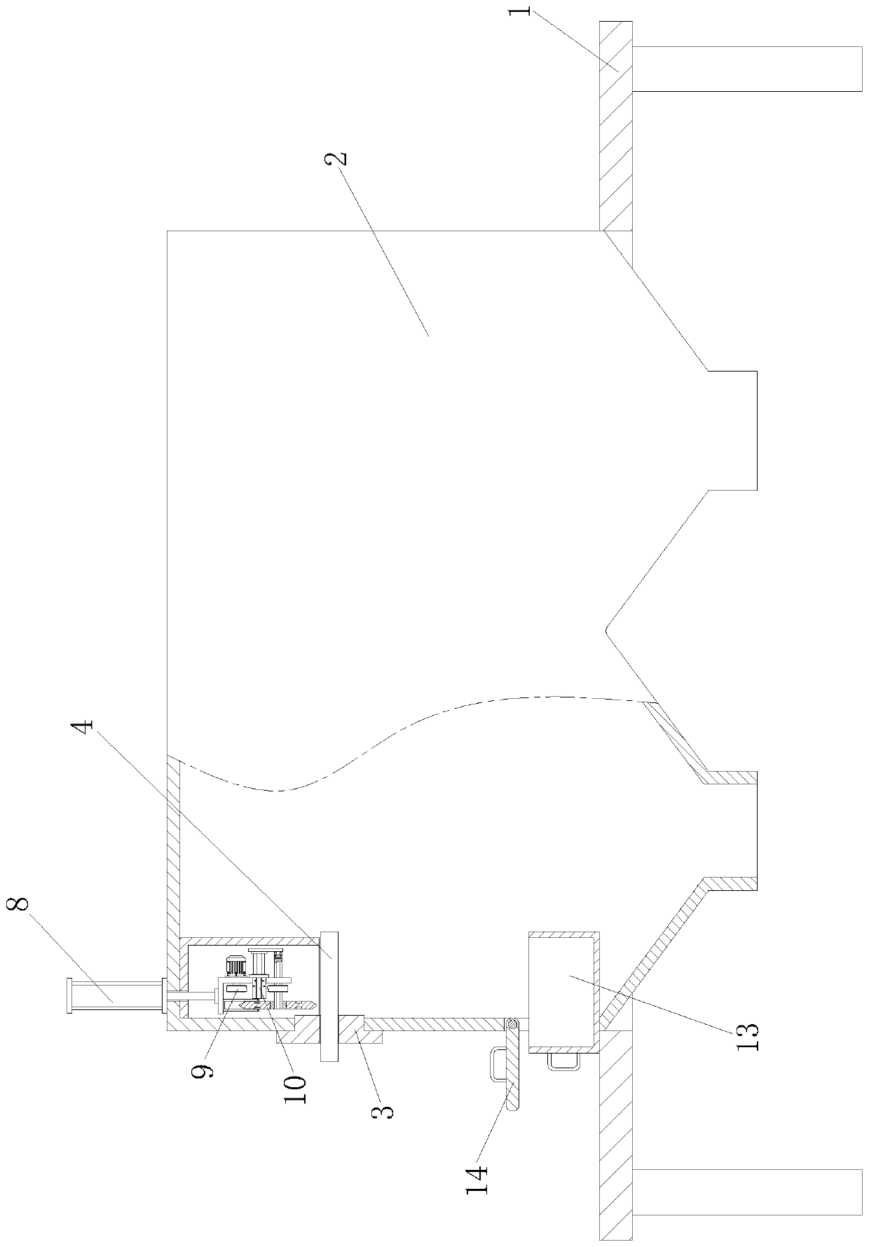
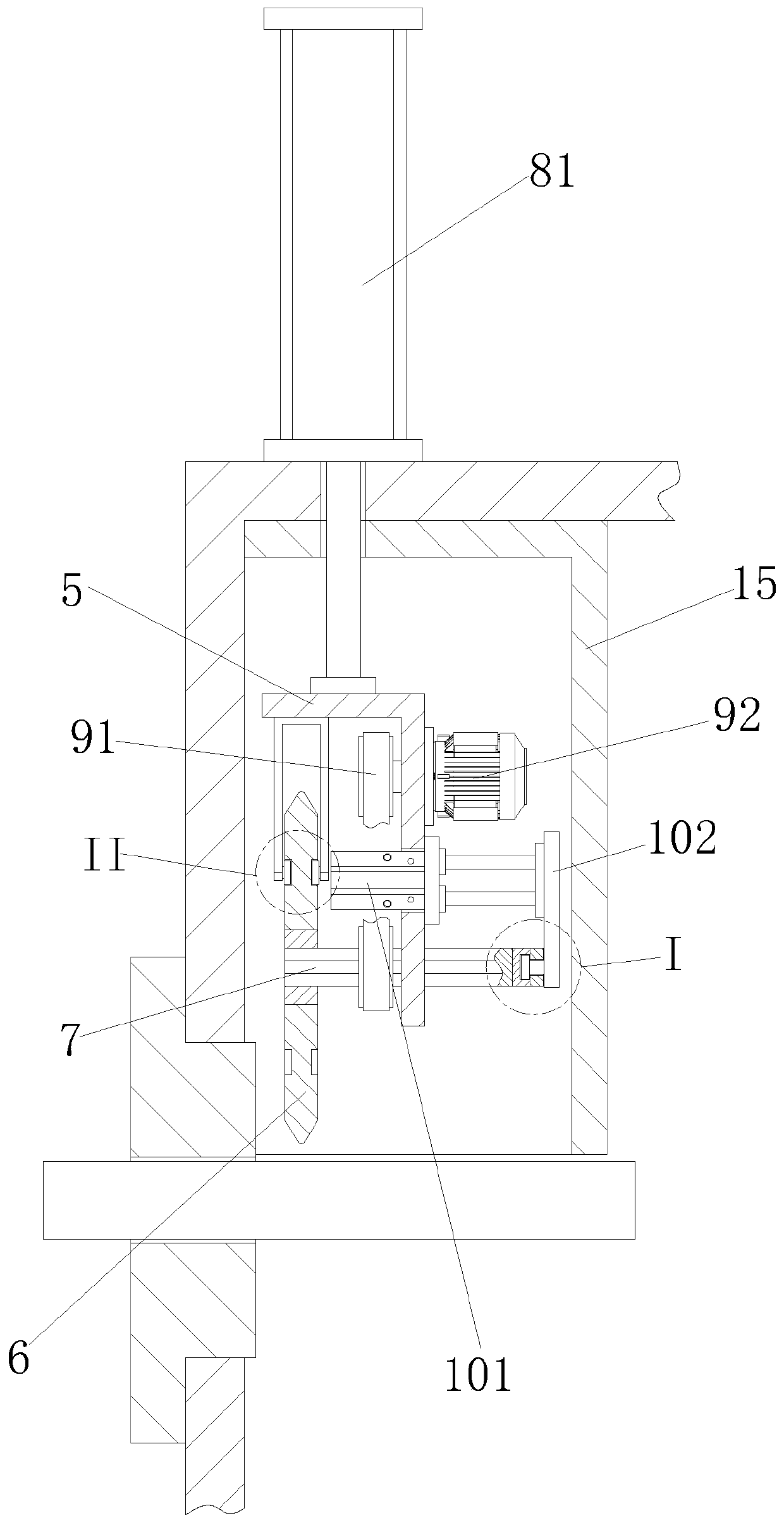
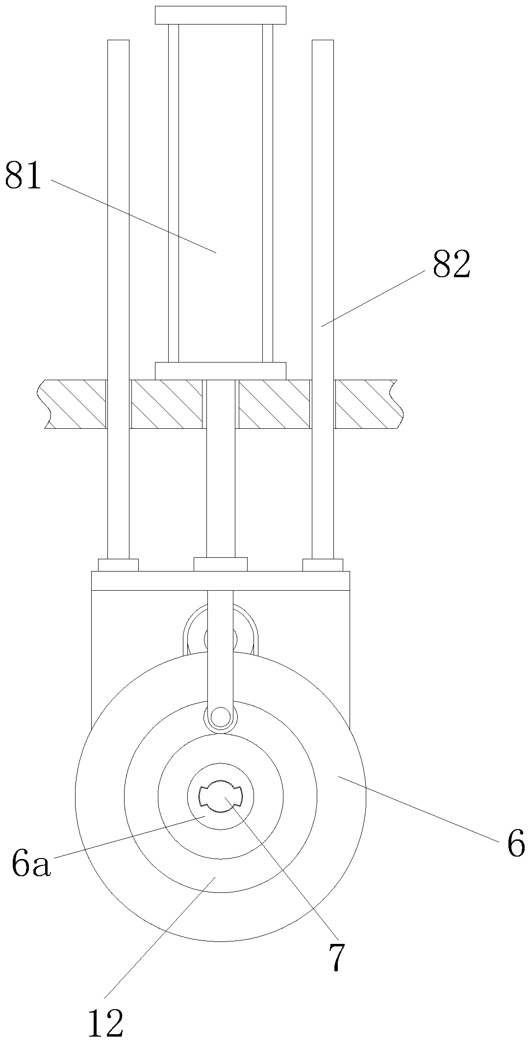
[0020] Such as Figure 1 to Figure 6 As shown, the dismantling device for the graphite conduit after being convenient to damage includes a bracket 1, a screening frame 2 is provided on the bracket 1, a fixing flange 3 is provided on the screening frame 2, and a fixing flange 3 is provided in the fixing flange 3 The graphite tube 4 for transporting high-temperature liquid metal also includes an L-shaped support plate 5 distributed in the screening frame 2. The support...


PUM


Abstract

The invention relates to a device for conveniently demounting a damaged graphite guide tube. The device comprises a bracket, a screening frame is arranged on the bracket, a fixed flange is arranged onthe screening frame, and the fixed flange is internally provided with the graphite tube for conveying high temperature liquid metal; and the device further comprises a supporting plate distributed inthe screening frame and having the L-shaped section, the supporting plate is provided with a cutting wheel for cutting off the graphite tube and a spline shaft matched with the cutting wheel, the screening frame is provided with a lifting mechanism for driving the L-shaped supporting plate to ascend and descend, the supporting plate is provided with a power mechanism for driving the cutting wheelto rotate, and the supporting plate is provided with a jacking-out mechanism for driving the spline shaft to slide to completely jack the graphite tube out of the fixed flange. According to the device, a hydraulic cylinder drives the cutting wheel to cut off the deformation part of the graphite tube, then an air cylinder drives the spline shaft to jack the graphite tube out of the fixed flange, the situation that the fixed flange is manually demounted and then cutting is conducted is not needed, the replacing steps are reduced, the replacing speed is increased, and orderly production is ensured.

Description

technical field [0001] The invention relates to the field of metal powder collection, in particular to a device for facilitating the removal of damaged graphite conduits. Background technique [0002] The metal block is smelted into a liquid state, and then the metal solution is atomized into metal powder through low-temperature nitrogen cooling, which is recovered by gravity screening, and a graphite tube for transporting the metal solution is installed on the screening frame; due to the high temperature of the metal solution, the graphite tube is in After a long time of use, it is easy to deform, resulting in incomplete atomization and blocking the graphite tube. After a long time of use, the graphite tube needs to be replaced. At present, it is mainly disassembled and replaced manually. The steps are cumbersome and the replacement time is long, which affects the normal production and processing. Therefore, the design is convenient for dismounting the damaged graphite cond...

Claims


Application Information

Patent Timeline
Patent Type & Authority Applications(China)
IPC IPC(8): B28D1/24B28D7/04B28D7/00
CPCB28D1/24B28D7/00B28D7/04
Inventor 程敬卿王蓉蓉
Owner 安徽鼎恒再制造产业技术研究院有限公司
Learn More