Rectifying method using dynamic monitoring and dynamic reinforcement

A dynamic monitoring and dynamic technology, applied in the field of steel structure correction, can solve problems such as excessive time and manpower consumption, secondary settlement of steel structures, large excavation depth, etc., to reduce construction difficulty, improve overall rigidity, and improve accuracy Effect

Active Publication Date: 2020-05-08
杭州敦固建筑特种工程有限公司
View PDF8 Cites 3 Cited by
  • Summary
  • Abstract
  • Description
  • Claims
  • Application Information

AI Technical Summary

Problems solved by technology

However, when the penetration depth of the pile foundation of the steel structure is large, the excavation depth during the correction process will be very large

Method used


Image

  • Rectifying method using dynamic monitoring and dynamic reinforcement
  • Rectifying method using dynamic monitoring and dynamic reinforcement
  • Rectifying method using dynamic monitoring and dynamic reinforcement

Examples


Embodiment Construction

[0050] The present invention will be described in further detail below in conjunction with the accompanying drawings.

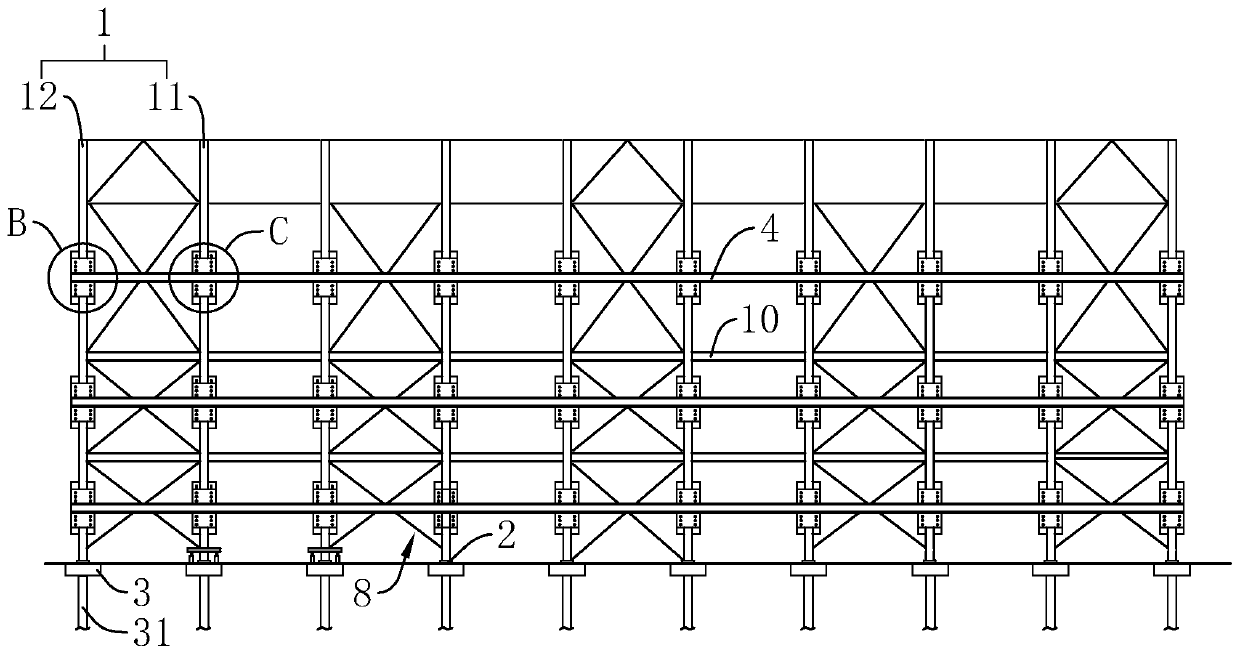
[0051] refer to figure 1 , which is a deviation correction method using dynamic monitoring and dynamic reinforcement disclosed by the present invention, comprising the following steps:

[0052] S1, measurement;

[0053] Carry out stakeout measurement on the steel column 1, determine the settlement of each steel column 1, and determine the steel column 1 that needs to be corrected according to the design requirements, and record these steel columns 1 that need to be corrected as the correction column 11, and the rest do not need to be corrected The steel column 1 for deflection correction is recorded as the in-situ column 12 . In the following description, the steel column 1 refers to the deviation correction column 11 and the in-situ column 12 .

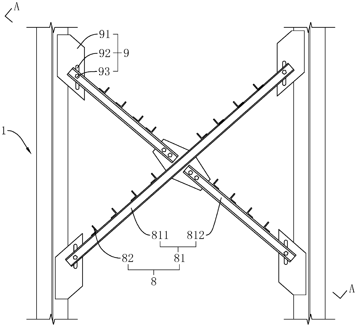
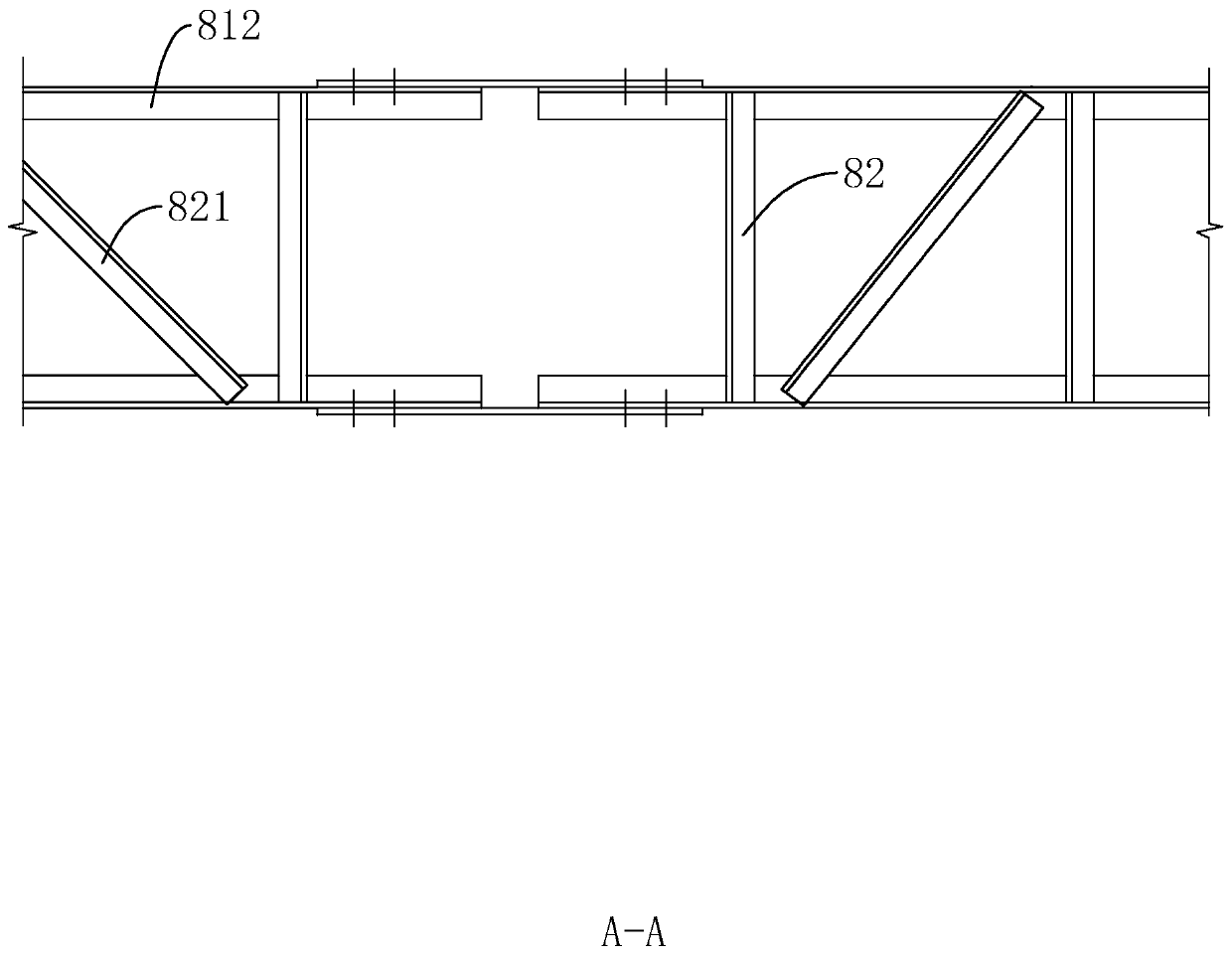
[0054] S2, support between columns;

[0055] combine figure 2 with image 3 , Install diagonal braces 8 b...


PUM


Abstract

The invention relates to a rectifying method using dynamic monitoring and dynamic reinforcement. The rectifying method comprises the following steps: S1, measurement is conducted, specifically, the settlement amount of steel columns is monitored, the steel columns needing to be rectified are determined and recorded as rectifying columns, and the remaining steel columns are recorded as in-situ columns; S2, column bracing is conducted, specifically, horizontal extension beams are mounted on the steel columns on the same side of a steel structure, the extension beams are fixedly connected with the in-situ columns, the extension beams limit horizontal displacement of the rectifying columns, and the rectifying columns can move in the vertical direction; S3, equipment mounting is conducted, specifically, force transmission frames are fixed to the bottoms of the rectifying columns, jacking appliances are mounted between the force transmission frames and bearing platforms, and the two or morejacking appliances are arranged; and S4, settlement rectifying of the rectifying columns is conducted, specifically, connecting steel plates at the bottoms of the rectifying columns and the bearing platforms are disconnected, the lifting appliances are started to drive the rectifying columns to move upwards until the rectifying columns reach the designed height. The force transmission frames are jacked to drive the rectifying columns to move upwards, so that a foundation pit with the large depth does not need to be excavated in the rectifying process, and the construction efficiency can be improved.

Description

technical field [0001] The invention relates to the technical field of deviation correction of steel structures, in particular to a deviation correction method using dynamic monitoring and dynamic reinforcement. Background technique [0002] Steel structure is a structure composed of steel materials, which is one of the main types of building structures. [0003] like Figure 9 As shown, the steel structure generally includes a foundation, steel columns 1 , steel beams 10 and a truss roof 101 . The foundation usually adopts an independent foundation, that is, a cap 3 is supported at the bottom of each steel column 1 , and several piles 31 are supported under the cap 3 . Adjacent caps 3 are connected through ground beams to improve the integrity of the connection between the steel columns 1 . Steel columns 1 and steel beams 10 are usually made of H-shaped steel. The bottom of the steel column 1 is usually welded with a connecting steel plate 2 perpendicular to it, and the ...

Claims


Application Information

Patent Timeline
IPC IPC(8): E02D35/00
CPCE02D35/00
Inventor 石敦敦刘春菊许卫峰夏育火吴滨涛彭程娟余致武朱旭浩
Owner 杭州敦固建筑特种工程有限公司
Why Eureka
Try Eureka