

Transverse beam guide rails apparatus
A technology of rail device and beam, which is applied in the directions of large fixed members, metal processing machinery parts, metal processing equipment, etc., can solve the problem of low overall stiffness, and achieve the effect of small overall stiffness, improved overall stiffness, and large overturning moment.
- Summary
- Abstract
- Description
- Claims
- Application Information
AI Technical Summary
Problems solved by technology
Method used
Image

Examples
Embodiment Construction
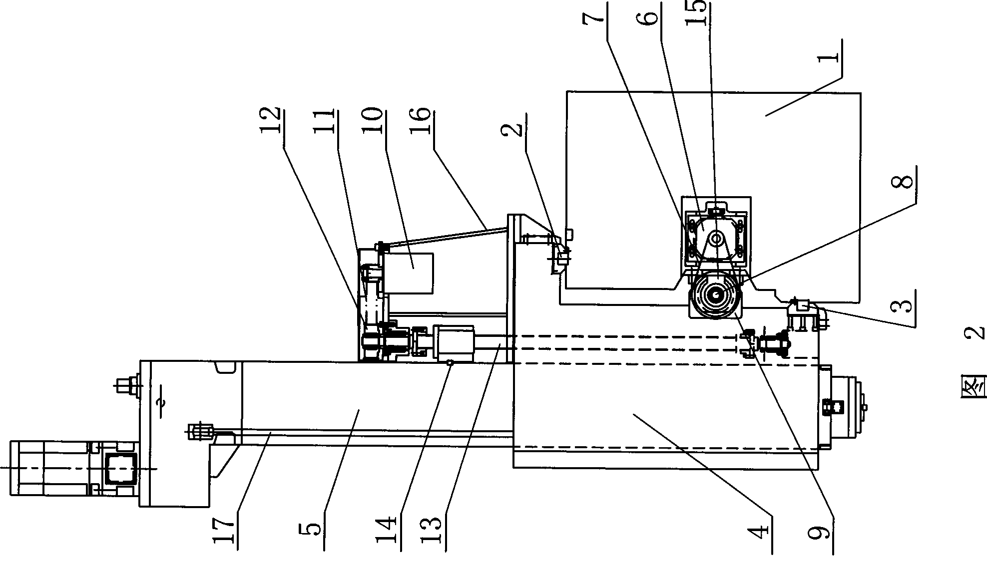
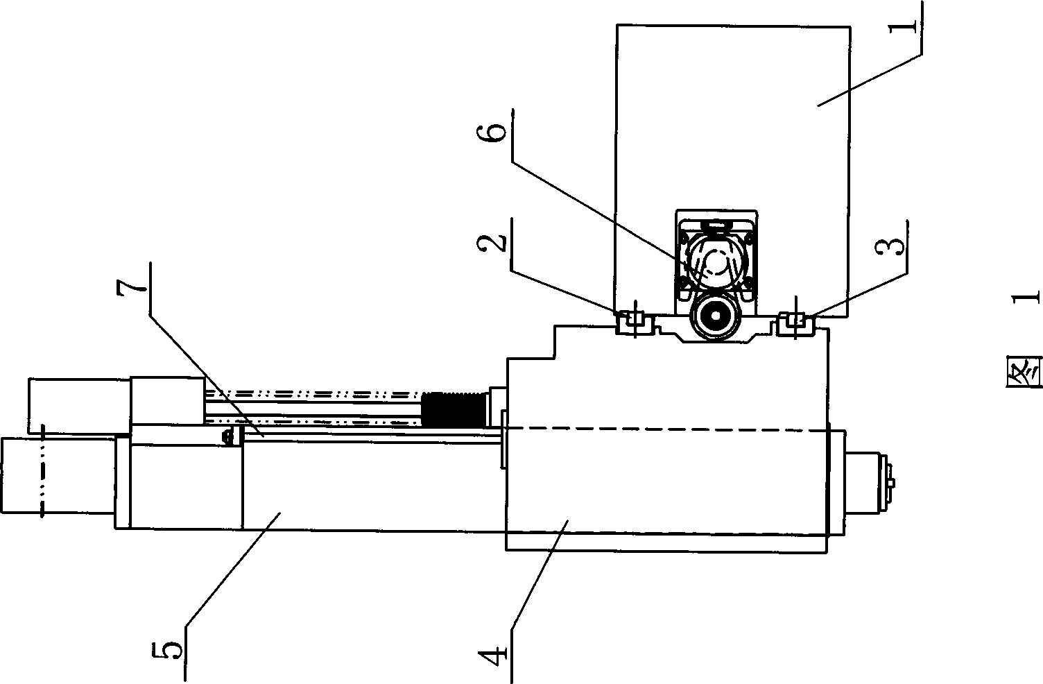
[0010] See Figure 2, the present invention includes a carriage 4, a ram 5, and a beam 1. The carriage 4 is installed on the beam 1 through a sliding pair, and the beam 1 is connected to the carriage 4 through a driving mechanism. The sliding pair includes an upper slide rail 2 and a lower slide rail 3. , The upper slide rail 2 and the lower slide rail 3 are installed on the top and the side of the crossbeam 1 respectively, and the upper slide rail 2 and the lower slide rail 3 are mounted on the chute on the carriage 4 respectively. The driving mechanism includes a servo motor 6, the servo motor 6 is installed on the beam 1, the servo motor 6 is connected to the ball screw 8 through the timing belt 7 and the pulley 15, the ball screw 8 is equipped with a screw nut 9 outside, and the screw nut 9 is connected with the The carriage 4 is connected; the ram 5 is installed on the chute in the carriage 4, and the carriage 4 and the ram 5 are connected by a transmission mechanism; the t...
PUM
 Abstract
Description
Claims
Application Information