Composite back-cable-free cable-stayed bridge and construction method thereof

A cable-free, cable-stayed bridge technology, applied in the field of bridge engineering, can solve the problems of inability to take into account the height and span of the tower, loss of structural strength, and large size of the tower body, so as to improve the landscape, reduce construction risks, reduce Effect of small main tower size

Active Publication Date: 2021-07-02
中冶南方城市建设工程技术有限公司 +1
View PDF6 Cites 0 Cited by
  • Summary
  • Abstract
  • Description
  • Claims
  • Application Information

AI Technical Summary

Problems solved by technology

Conventional cable-stayed bridges without back cables often choose a relatively bloated bridge tower, and the size of the main girder is also large. In terms of height, it is impossible to take into account whether the ratio of tower height to span is coordinated, which loses the inherent strength of the structure.
Especially when the main girder adopts steel structure, the light steel structure main girder reduces the construction difficulty of the bridge tower; the bridge tower is inclined at a certain angle, although the cable force can be balanced by the self-weight of the tower body; but the weight requirement of the tower body also determines the body size will be larger

Method used


Image

  • Composite back-cable-free cable-stayed bridge and construction method thereof
  • Composite back-cable-free cable-stayed bridge and construction method thereof
  • Composite back-cable-free cable-stayed bridge and construction method thereof

Examples


Embodiment Construction

[0034] The present invention will be described in detail below in conjunction with the accompanying drawings and embodiments.

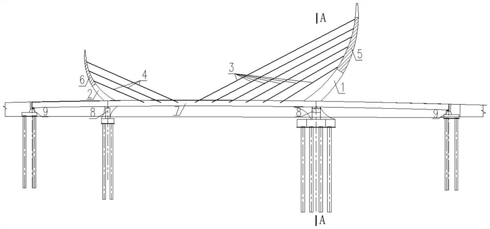
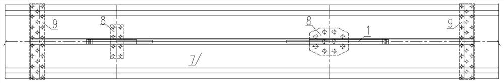
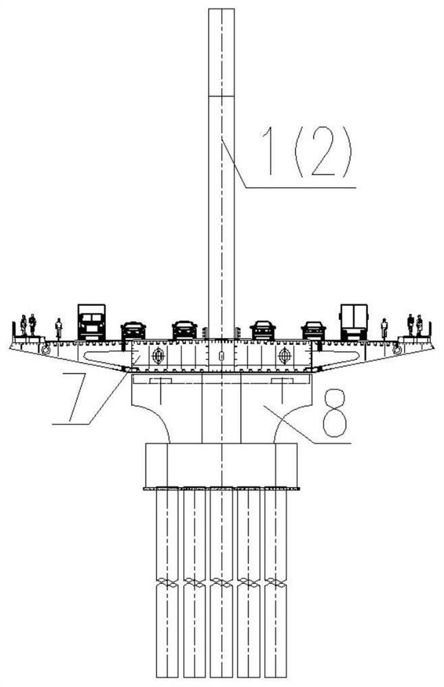
[0035] refer to Figure 1 ~ Figure 3 As shown, the compound non-back cable-stayed bridge in an embodiment provided by the present invention includes a steel structure girder 7, a steel structure stressed main tower 1, a steel structure stressed auxiliary tower 2, a pier structure 8 and an abutment Structure, the steel structure main tower 1 and the steel structure auxiliary tower 2 are sequentially arranged on the steel structure main girder 7 along the bridge direction, and the bottom of the steel structure main girder 7 is provided with a pier structure 8 and an abutment structure;

[0036] A main tower stay cable 3 is connected between the main steel structure stressed tower 1 and the steel structure main beam 7 , and an auxiliary tower stay cable 4 is connected between the steel structure stressed auxiliary tower 2 and the steel structure main bea...


PUM


Abstract

The invention discloses a composite back-cable-free cable-stayed bridge. The cable-stayed bridge comprises a steel structure main beam, a steel structure stress main tower, a steel structure stress auxiliary tower, a bridge pier structure and a bridge abutment structure, the steel structure stress main tower and the steel structure stress auxiliary tower are sequentially arranged on the steel structure main beam in the bridge direction, and the bridge pier structure and the bridge abutment structure are arranged at the bottom of the steel structure main beam; and a main tower stay cable is connected between the steel structure stress main tower and the steel structure main beam, an auxiliary tower stay cable is connected between the steel structure stress auxiliary tower and the steel structure main beam, a main tower micro-expansion concrete pouring section is poured into the steel structure stress main tower, and an auxiliary tower micro-expansion concrete pouring section is poured into the steel structure stress auxiliary tower. The cable-stayed bridge can meet the use requirement for long-term service; and the landscape performance is good, the construction risk is low, and economical efficiency is good.

Description

technical field [0001] The invention relates to the technical field of bridge engineering, in particular to a composite non-back cable-stayed bridge and a construction method thereof. Background technique [0002] In urban bridge construction and transportation, bridge design no longer simply pursues economy and practicality, but begins to pursue the bridge landscape effect of "one bridge, one scene". Among them, the cable-stayed bridge is a bridge type with strong spanning ability and good landscape, and it is constantly used in urban bridges. In recent years, with the rapid development of my country's bridge industry, various bridge types of cable-stayed bridges have emerged in an endless stream, and the requirements for bridge shape design to gradually conform to aesthetics have become increasingly strong. [0003] Conventional pylons of cable-stayed bridges without back cables rely on the self-weight of the pylon, so each section of the pylon must correspond to the hori...

Claims


Application Information

Patent Timeline
Patent Type & Authority Applications(China)
IPC IPC(8): E01D11/04E01D19/00E01D21/00E01D19/14E01D19/16E01D19/02
CPCE01D11/04E01D19/00E01D21/00E01D19/14E01D19/16E01D19/02
Inventor 程建波刘宇闻程小亮陈维王存杨旭胡春
Owner 中冶南方城市建设工程技术有限公司
Why Eureka
Try Eureka