

Closed circulating turbine power generating system rotor structure based on air bearing
A power generation system, closed cycle technology, applied to the components of the pumping device for elastic fluid, non-variable displacement pump, engine components, etc., can solve the problems affecting the working reliability and connection strength of the closed cycle turbine power generation system. And the stiffness is not guaranteed, the interference of the connection part is reduced, etc., to achieve the effect of repeatable assembly, enhanced stability and reliability, and reduced wear and tear
- Summary
- Abstract
- Description
- Claims
- Application Information
AI Technical Summary
Problems solved by technology
Method used
Image

Examples
Embodiment Construction
[0033] It should be noted that, in the case of no conflict, the embodiments of the present invention and the features in the embodiments can be combined with each other.
[0034] The present invention will be described in detail below with reference to the accompanying drawings and examples.
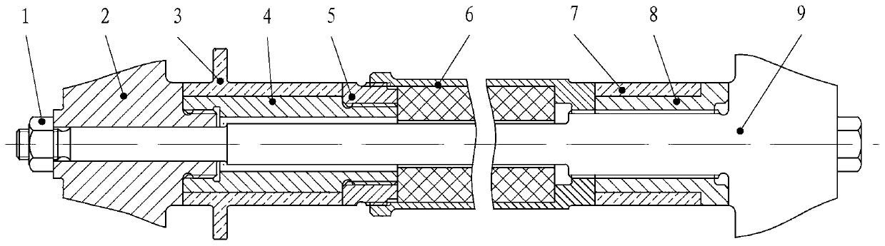
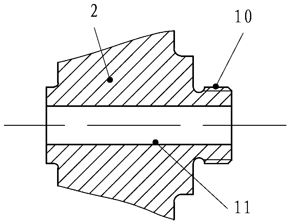
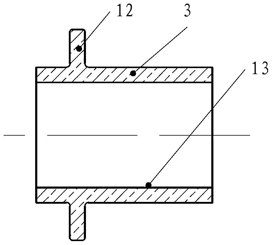
[0035] A closed cycle turbine power generation system rotor structure based on air bearings, including lock nut 1, compressor impeller 2, composite bushing 3, connecting bushing 4, transition bushing 5, motor shaft 6, fixed bushing 7 , Radial bushing 8 and turbine rotor 9. The direction of rotation of the locking nut 1 is opposite to that of the rotor of the turbine power generation system; thread 10; the composite shaft sleeve 3 has an annular end face 12 co-axial with the thrust bearing, the composite shaft sleeve 3 is made of wear-resistant and high temperature resistant ceramic material, and the composite shaft sleeve 3 passes through the inner hole 13 Assembled on the connecting s...
PUM
 Abstract
Description
Claims
Application Information