
Multi-gear combined type transmission with prepositioned auxiliary box

A combination and transmission technology, applied in the direction of instruments, transmission devices, mechanical control devices, etc., can solve the problems of insufficient power for side installation, inconvenient transmission, and increase the inclination angle of the chassis drive shaft, so as to increase the transmission system The effect of transmission ratio, improvement of dynamic state, and increase of overall rigidity

Inactive Publication Date: 2010-01-20
綦江南方汽车齿轮有限公司
View PDF0 Cites 3 Cited by
  • Summary
  • Abstract
  • Description
  • Claims
  • Application Information

AI Technical Summary

Problems solved by technology

[0004] At present, the sub-boxes of the transmission are mostly installed on the side or rear of the main box of the transmission. According to the different installation positions, the effects achieved are also different. Among them, the power of the side installation is not enough for the power take-off and the transmission is inconvenient after the power take-off. , prone to overload damage, the rear-mounted installation shortens the distance from the output power of the transmission to the drive axle and increases the inclination angle of the chassis drive shaft, which not only affects the driving safety of the car, but also has little room for improvement in the climbing ability of the car Big

Method used


Image

  • Multi-gear combined type transmission with prepositioned auxiliary box
  • Multi-gear combined type transmission with prepositioned auxiliary box
  • Multi-gear combined type transmission with prepositioned auxiliary box

Examples


Embodiment Construction

[0021] Hereinafter, preferred embodiments of the present invention will be described in detail with reference to the accompanying drawings. It should be understood that the preferred embodiments are only for illustrating the present invention, but not for limiting the protection scope of the present invention.

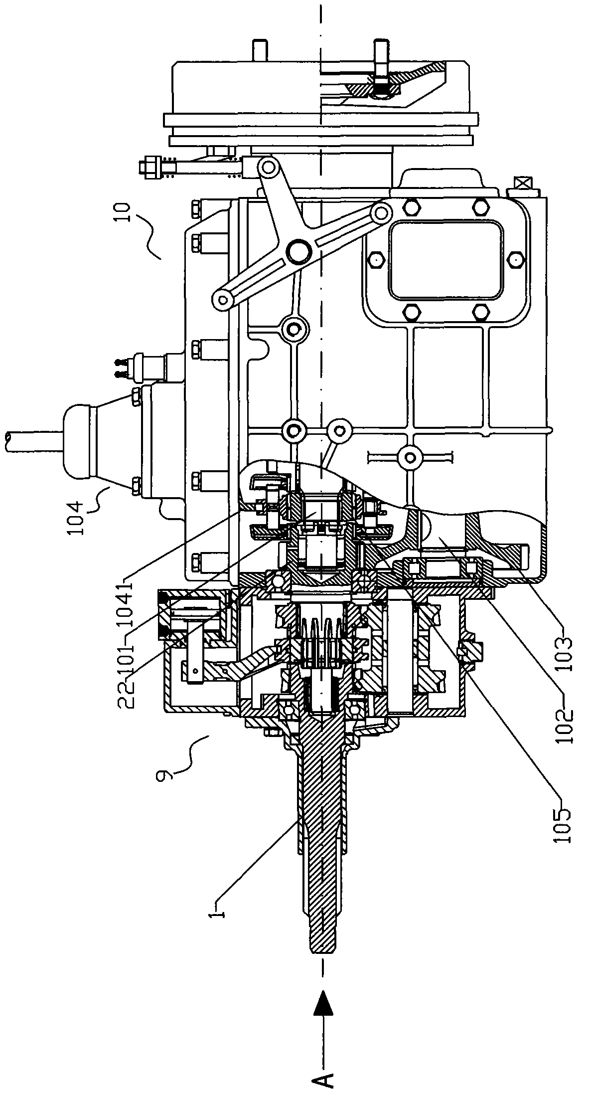
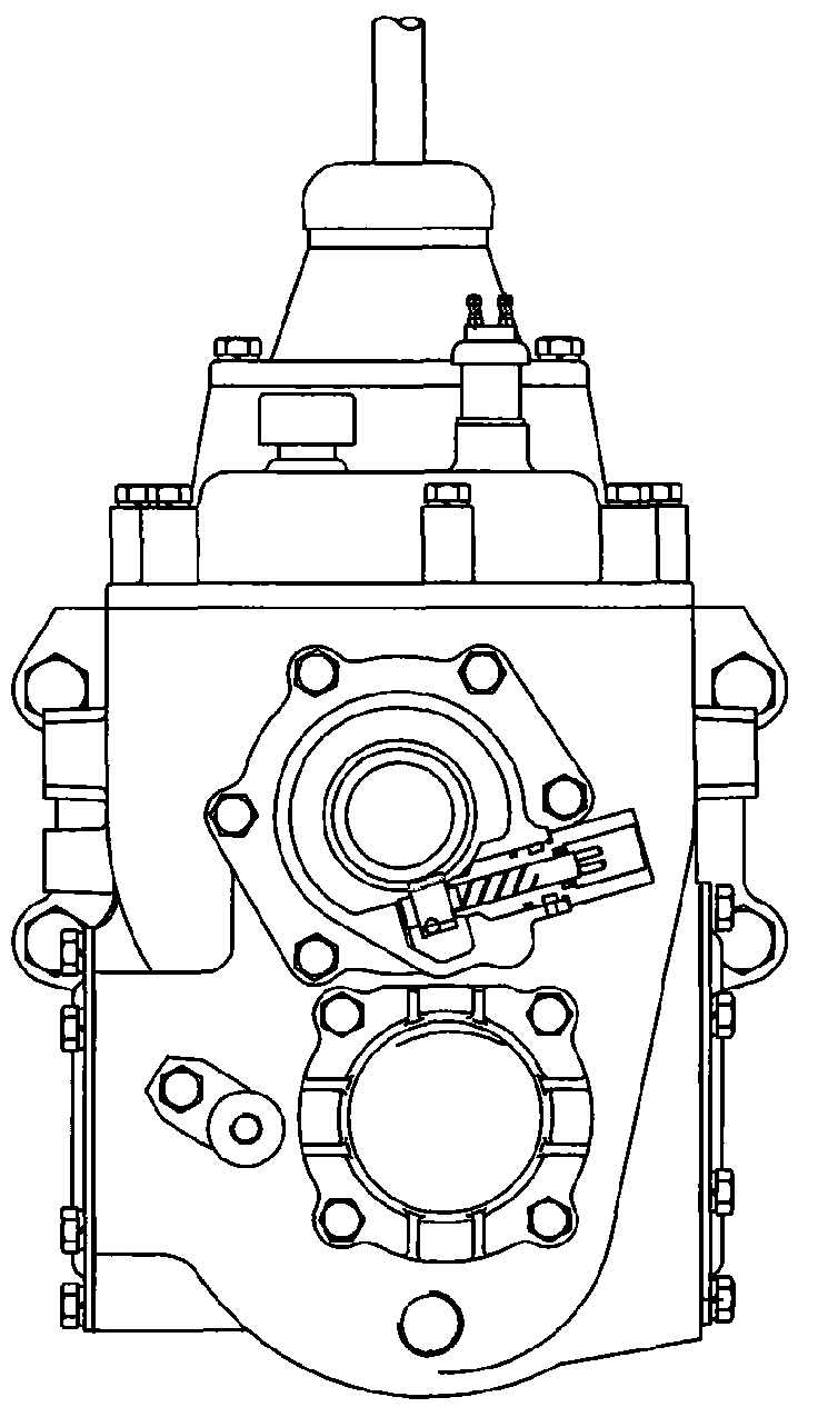
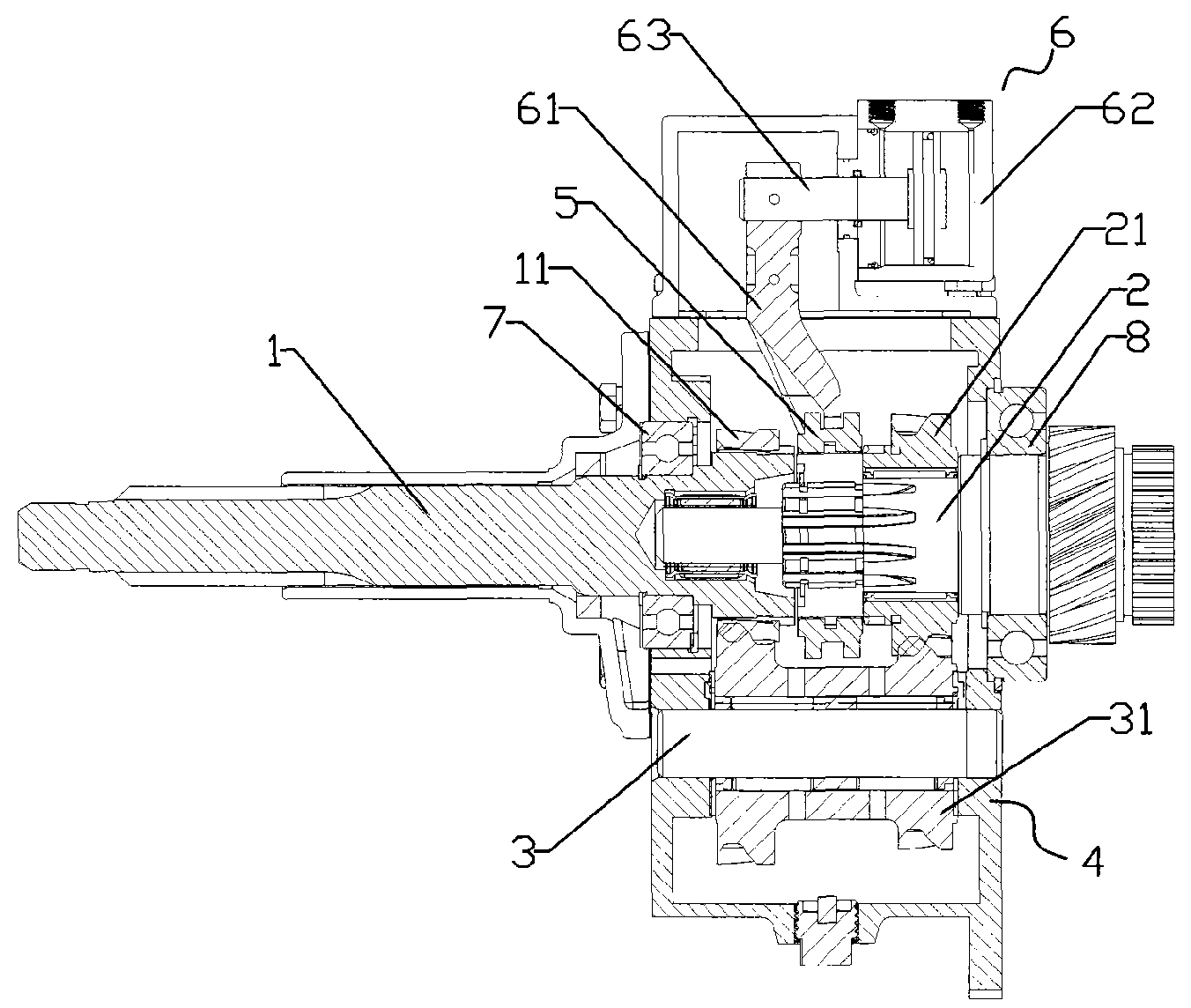
[0022] like figure 1 and figure 2 As shown, the present invention is made up of five-speed main transmission main box 10 and two-speed auxiliary transmission auxiliary box 9, wherein, main box 10 comprises main box transmission shaft 101, and reverse gear, low gear are respectively housed on the main box transmission shaft 1st gear, 2nd gear, 3rd gear, there is a sliding sleeve between the low and reverse gears, between the 1st and 2nd gears, and between the 3rd and 4th gears, respectively set a sliding sleeve or a synchronizer Engage.

[0023] Below the main box transmission shaft 101 are provided with the main box intermediate shaft 102, the main box intermediate...


PUM


Abstract

The invention discloses a multi-gear combined type transmission with a prepositioned auxiliary box, comprising a main box and an auxiliary box, wherein the auxiliary box is prepositioned at the front end face of the main box, a main shaft of the auxiliary box is engaged with a transmission gear of a middle shaft of the main box by a shaft gear of the main shaft of the auxiliary box, and the power of an external engine is output to the middle shaft of the main box by the main shaft of the auxiliary box after the power of the external engine is transmitted to a shaft of the auxiliary box by a clutch. The invention adopts the mode of the prepositioned auxiliary box, diminishes the size of a box body of a gearbox, diminishes the length of an output shaft simultaneously, and increases the integral rigidity; the auxiliary box of the invention has a high-gear speed ratio and a low-gear speed ratio; and when the condition of a road is poor, an auxiliary gearbox is changed to low gear, which can increase the transmission ratio of a transmission system, improve the power state, thereby greatly increasing the traction force of a modification vehicle on the original basis and effectively enhancing the climbing ability of the vehicle.

Description

technical field [0001] The invention relates to a multi-speed combined auxiliary box front transmission. Background technique [0002] With the development of social economy, automobiles are becoming more and more popular in rural areas and become the main means of transportation in rural areas and mountainous areas. Taking the agricultural vehicles converted from the chassis of domestic medium-sized trucks as an example, in mountainous areas with poor road conditions, there is a fatal weakness of insufficient climbing ability. [0003] In order to ensure that the car has a good climbing ability, taking into account power, economy and acceleration, it is necessary to expand the range of transmission ratio and increase the number of gears. In order to avoid the structure of the transmission being too complicated and to facilitate serial production, combined mechanical transmissions are often used. That is to say, with one or two types of 4-6 speed transmissions as the main ...

Claims


Application Information

Patent Timeline
IPC IPC(8): F16H3/08F16H3/12F16H63/32F16H63/04
Inventor 杨光能
Owner 綦江南方汽车齿轮有限公司
Learn More