System and method for dynamic monitoring of water pressure and flow velocity behind tunnel lining and dredging and drainage

A dynamic monitoring and drainage system technology, applied in drainage, earth square drilling, mining equipment, etc., can solve the problems of small blind pipe coverage area, difficulty in finding the blocked location of drainage pipes, and reduced drainage capacity, so as to achieve easy operation and maintenance, and realize Operation and maintenance, and the effect of improving drainage capacity

Active Publication Date: 2021-03-30
SHANDONG TRAFFIC PLANNING DESIGN INST
View PDF5 Cites 0 Cited by
  • Summary
  • Abstract
  • Description
  • Claims
  • Application Information

AI Technical Summary

Problems solved by technology

At present, the existing tunnel circumferential drainage system is relatively simple, mainly the circumferential spring blind pipe, the blind pipe covers a small area, has no flow collecting function, and the water flow behind the tunnel lining cannot effectively flow into the longitudinal drainage pipe; Waterstops are often only used for waterproofing treatment of tunnel construction joints and settlement joints, and have no diversion function. When the construction quality of the back-adhesive waterstop is poor, the water behind the lining often seeps into the tunnel through the construction joints
[0004] In extreme meteorological disasters such as sudden rainstorms, due to the saturated operation of the tunnel waterproof system, the accumulated water behind the lining cannot be discharged in time, and the water pressure increases sharply in a short period of time. The tunnel lining is subjected to high water pressure, which often leads to cracking of the tunnel lining, When the waterproof board fails, the solution is usually to drill holes in the lining for drainage to reduce the water pressure behind the lining, but drilling will cause structural damage to the lining; at the same time, when the tunnel has been in operation for a long time, the longitudinal drainage system often Partial clogging occurs, resulting in a reduction in the cross-section of the water, greatly reducing the drainage capacity, and will also increase the water pressure behind the tunnel lining, resulting in damage to the drainage system. Since the drainage system behind the tunnel is located inside the tunnel lining, it is difficult to find the location of the blockage of the drainage pipe. Therefore, the blockage cannot be cleaned in time

Method used


Image

  • System and method for dynamic monitoring of water pressure and flow velocity behind tunnel lining and dredging and drainage
  • System and method for dynamic monitoring of water pressure and flow velocity behind tunnel lining and dredging and drainage
  • System and method for dynamic monitoring of water pressure and flow velocity behind tunnel lining and dredging and drainage

Examples


Embodiment

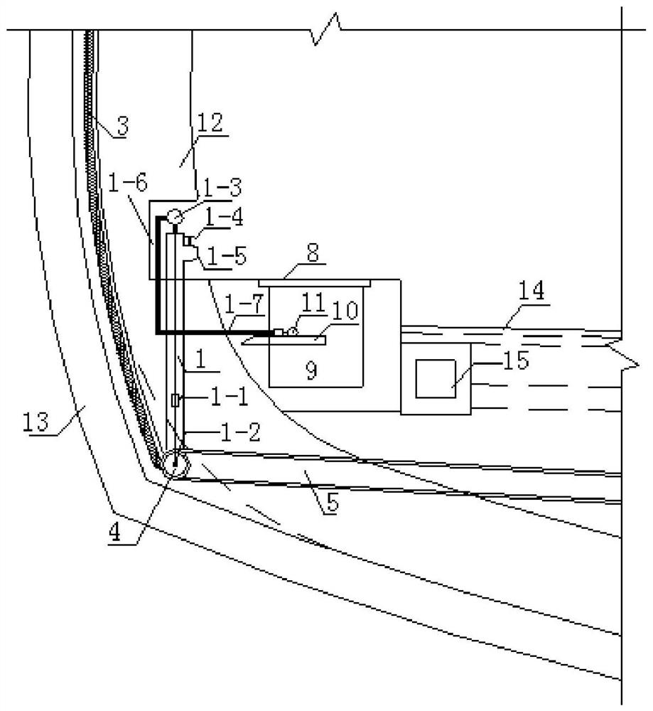
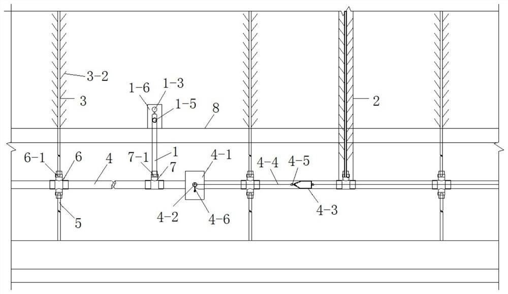
[0061] Such as figure 1 with figure 2 As shown, the water pressure and flow velocity dynamic monitoring and drainage system behind the tunnel lining implemented in this implementation is composed of a circular diversion drainage system, a water pressure-flow velocity monitoring system, a longitudinal drainage system, a horizontal drainage system, and a drainage system. Drainage system, horizontal drainage system, water pressure-flow velocity monitoring system 1 can be connected with vertical drainage pipe through four-way 6 or three-way 7 .

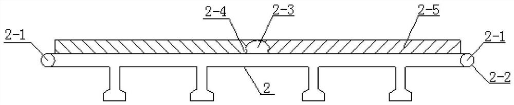
[0062] Such as Figure 5 with Image 6 As shown, the circumferential drainage system is composed of a back-mounted waterstop 2 and a circumferential drainage pipe 3, and several circumferential drainage pipes 3, such as 2, 3, 4, 5 or more, according to the tunnel The length and the specific construction environment determine the specific quantity, distributed in the length direction of the tunnel, and each circumferential drain pipe 3...


PUM


Abstract

The invention discloses a dynamic monitoring, dredging and drainage guiding method for the back water pressure and flow rate of a tunnel lining. The dynamic monitoring, dredging and drainage guiding method for the back water pressure and flow rate of the tunnel lining comprises the following steps that seeping water on the back of the lining is guided by a plurality of guide pipes of an annular drainage pipe to enter a main drainage pipe, then enters a longitudinal drainage pipe through the main drainage pipe and is discharged out of a tunnel through the longitudinal drainage pipe; and when the interior of the longitudinal drainage pipe is blocked, a flow rate sensor and a pressure sensor send out an abnormal signal, and then acting force is applied to rotors in a dredging structure to enable the rotors to move in the longitudinal drainage pipe in a fixed direction so as to push sewage in the longitudinal drainage pipe to a sewage discharging structure, so that the longitudinal drainage pipe is dredged. Water pressure and flow rate monitoring systems are distributed in the length direction of the longitudinal drainage pipe and corresponds to the rotors in position, so that regionalmonitoring and dredging of the tunnel are realized, a silted section can be accurately positioned and dredged in time, and operation maintenance of the tunnel can be realized more easily.

Description

technical field [0001] The invention relates to the technical field of road tunnel construction, operation and maintenance, in particular to a method for dynamic monitoring of water pressure and flow velocity behind the lining of the tunnel and a dredging and drainage method. Background technique [0002] The information disclosed in this background section is only intended to increase the understanding of the general background of the present invention, and is not necessarily taken as an acknowledgment or any form of suggestion that the information constitutes the prior art already known to those skilled in the art. [0003] Tunnel waterproofing and drainage engineering is an important task during tunnel construction and operation. Tunnel water leakage is one of the main diseases of tunnels during operation. There is a saying that ten tunnels and nine leaks. At present, the existing tunnel circumferential drainage system is relatively simple, mainly the circumferential spri...

Claims


Application Information

Patent Timeline
Patent Type & Authority Patents(China)
IPC IPC(8): E21F16/02E21F17/18
CPCE21F16/02E21F17/18
Inventor 孙昌海万利张伟张长安宋京吴涛刘传利沈佳佳邵行
Owner SHANDONG TRAFFIC PLANNING DESIGN INST
Why Eureka
Try Eureka