
Slope deformation monitoring device and method

A deformation monitoring and slope technology, applied in the direction of measuring devices, circuit devices, optical devices, etc., can solve the problems of high maintenance cost, laser ranging interference, high cost, etc., and achieve strong practicability and anti-interference ability, monitoring Large-scale, low-cost effects

Active Publication Date: 2021-03-16
HUNAN LIANZHI BRIDGE & TUNNEL TECH
View PDF10 Cites 0 Cited by
  • Summary
  • Abstract
  • Description
  • Claims
  • Application Information

AI Technical Summary

Problems solved by technology

[0002] The Chinese patent with the application number CN201921224251.2 discloses a long-distance non-contact visual slope monitoring device, which uses laser ranging monitoring technology to monitor the deformation of the slope, but there are generally vegetation, grass and trees on the slope It grows vigorously and is easy to block, which will interfere with laser ranging. It is often necessary to cut down the vegetation on the slope, which not only has high maintenance costs, but also increases the risk of slope landslides, and is not conducive to long-term slope monitoring; In addition, the core laser device in this solution often needs to be imported, and it has certain restrictions on distance and area monitoring. For a huge mountain slope, a large number of monitoring devices are required, which is expensive

Method used


Image

  • Slope deformation monitoring device and method
  • Slope deformation monitoring device and method
  • Slope deformation monitoring device and method

Examples


Embodiment

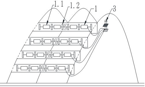
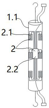
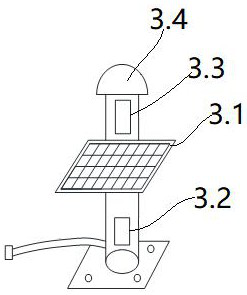
[0038] A slope deformation monitoring device, comprising a monitoring unit 2, a receiving unit 3 and multiple groups of reinforcement structures 1 arranged parallel to each other on the slope along the vertical direction, such as Figure 1-4 As shown, the details are as follows;

[0039] like figure 1 As shown, multiple sets of reinforcing structures 1 are parallel in the vertical direction, forming a contour-like structure in the vertical direction. Here, the vertical interval of the reinforcement structure is selected according to the actual situation.

[0040] like figure 1 As shown, the reinforcement structure 1 includes fixed piles 1.2 and multiple sets of pipe bodies 1.1; the slope is provided with grooves along the horizontal direction; The adjacent two groups of pipes of the group reinforcement structure are connected in series along the horizontal; the fixed piles are vertically inserted on the slope, and are located between the two groups of pipes horizontally, an...


PUM


Abstract

The invention discloses a slope deformation monitoring device which comprises a reinforcing structure, a monitoring unit and a receiving unit. The reinforcing structure comprises a plurality of sets of pipe bodies. The pipe bodies are horizontally arranged on a side slope, and every two adjacent sets of pipe bodies are connected in series in the horizontal direction. The monitoring unit comprisessensing pieces and an acquisition box; the sensing pieces are arranged on the inner walls of the pipe bodies; the acquisition box is electrically connected with the sensing pieces and is used for receiving slope deformation signals of the sensing pieces; the receiving unit is electrically connected with the acquisition box and used for receiving slope deformation signals of the acquisition box. The side slope can be reinforced through the multiple sets of pipe bodies; when landslide occurs, the slope acts on the outer walls of the pipe bodies, so that the pipe bodies deform, the sensing piecesacquire a pipe body deformation signal and transmit the pipe body deformation signal to an external background through the receiving unit, and the practicability and the anti-interference capacity are high. The invention further discloses a side slope deformation monitoring method, through the sequential obtaining mode, the side slope deformation can be monitored in real time on the premise of reducing power consumption, and therefore early prevention and early warning are achieved.

Description

technical field [0001] The invention relates to the technical field of slope monitoring, in particular to a slope deformation monitoring device and method. Background technique [0002] The Chinese patent with the application number CN201921224251.2 discloses a long-distance non-contact visual slope monitoring device, which uses laser ranging monitoring technology to monitor the deformation of the slope, but there are generally vegetation, grass and trees on the slope It grows vigorously and is easy to block, which will interfere with laser ranging. It is often necessary to cut down the vegetation on the slope, which not only has high maintenance costs, but also increases the risk of slope landslides, and is not conducive to long-term slope monitoring; In addition, the core laser device in this solution often needs to be imported, and it has certain limitations on distance and area monitoring. For a huge mountain slope, a large number of monitoring devices are required, and ...

Claims


Application Information

Patent Timeline
Patent Type & Authority Applications(China)
IPC IPC(8): G01B11/16H02J7/35G05B19/042
CPCG01B11/16G05B19/0423G05B2219/21001H02J7/35
Inventor 雷创业梁晓东熊用雷孟飞
Owner HUNAN LIANZHI BRIDGE & TUNNEL TECH
Learn More