Eureka AIR delivers breakthrough ideas for toughest innovation challenges, trusted by R&D personnel around the world.

Vehicle control system, vehicle and control method

A technology of a vehicle control system and a control method, applied in the vehicle control system, the vehicle and a control field, can solve the problems of inability to automatically control the fan speed, high fuel consumption, and high pressure of the air conditioning system

Active Publication Date: 2021-08-31
SANY SPECIAL PURPOSE VEHICLE CO LTD
View PDF5 Cites 0 Cited by
  • Summary
  • Abstract
  • Description
  • Claims
  • Application Information

AI Technical Summary

Problems solved by technology

[0002] The air-conditioning condenser of engineering vehicles mostly dissipates heat through the fan of the engine. When the air conditioner is turned on at idle speed, the condenser’s heat dissipation capacity is poor, resulting in high pressure on the air-conditioning system, which easily damages the compressor. Specifically, at idle speed, through condensation The wind speed in front of the condenser is small, and the heat dissipation of the condenser is poor, which will lead to an increase in the pressure of the air conditioning system
In response to this situation, the existing engineering vehicles have opened the air conditioner idle speed boost function, that is, when the air conditioner is turned on at idle speed, the speed of the engine fan is increased, thereby improving the heat dissipation capacity of the condenser and reducing the pressure of the air conditioning system. The pressure of the system is used to automatically control the speed of the fan, and the fuel consumption is high

Method used


Image

  • Vehicle control system, vehicle and control method
  • Vehicle control system, vehicle and control method
  • Vehicle control system, vehicle and control method

Examples


Embodiment Construction

[0032] In order to have a clearer understanding of the above objects, features and advantages of the present invention, the present invention will be further described in detail below in conjunction with the accompanying drawings and specific embodiments. It should be noted that, in the case of no conflict, the embodiments of the present application and the features in the embodiments can be combined with each other.

[0033] In the following description, many specific details are set forth in order to fully understand the present invention. However, the present invention can also be implemented in other ways different from those described here. Therefore, the protection scope of the present invention is not limited by the specific details disclosed below. EXAMPLE LIMITATIONS.

[0034] Refer below Figure 1 to Figure 6 Some embodiments according to the invention are described.

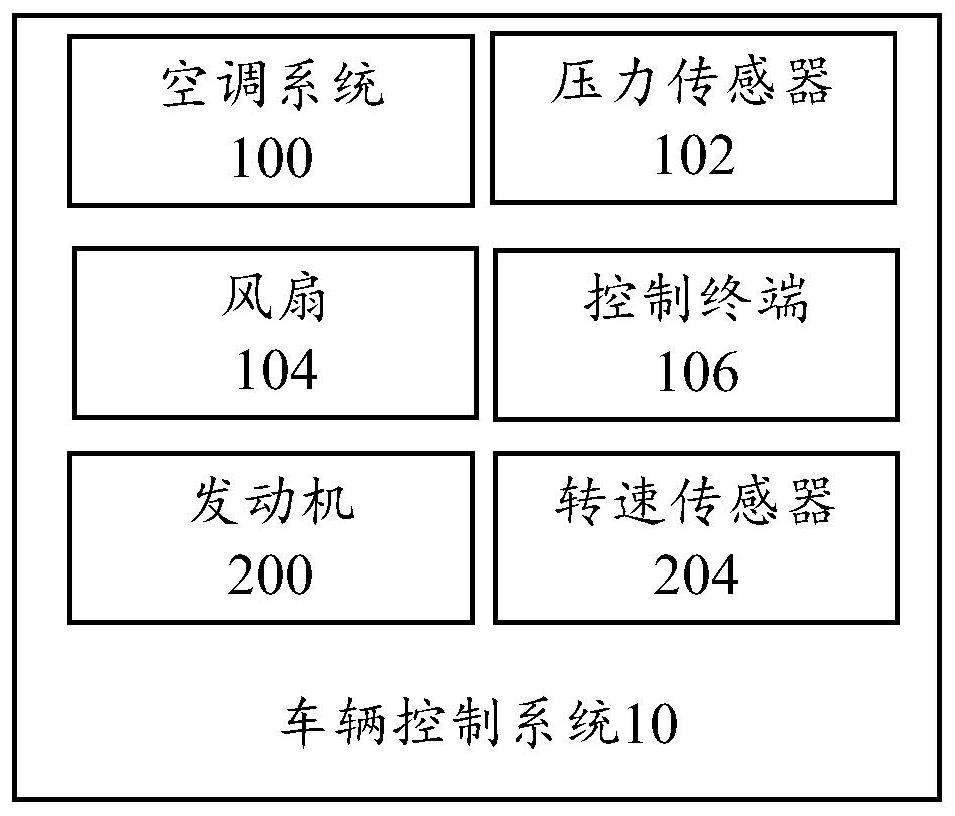
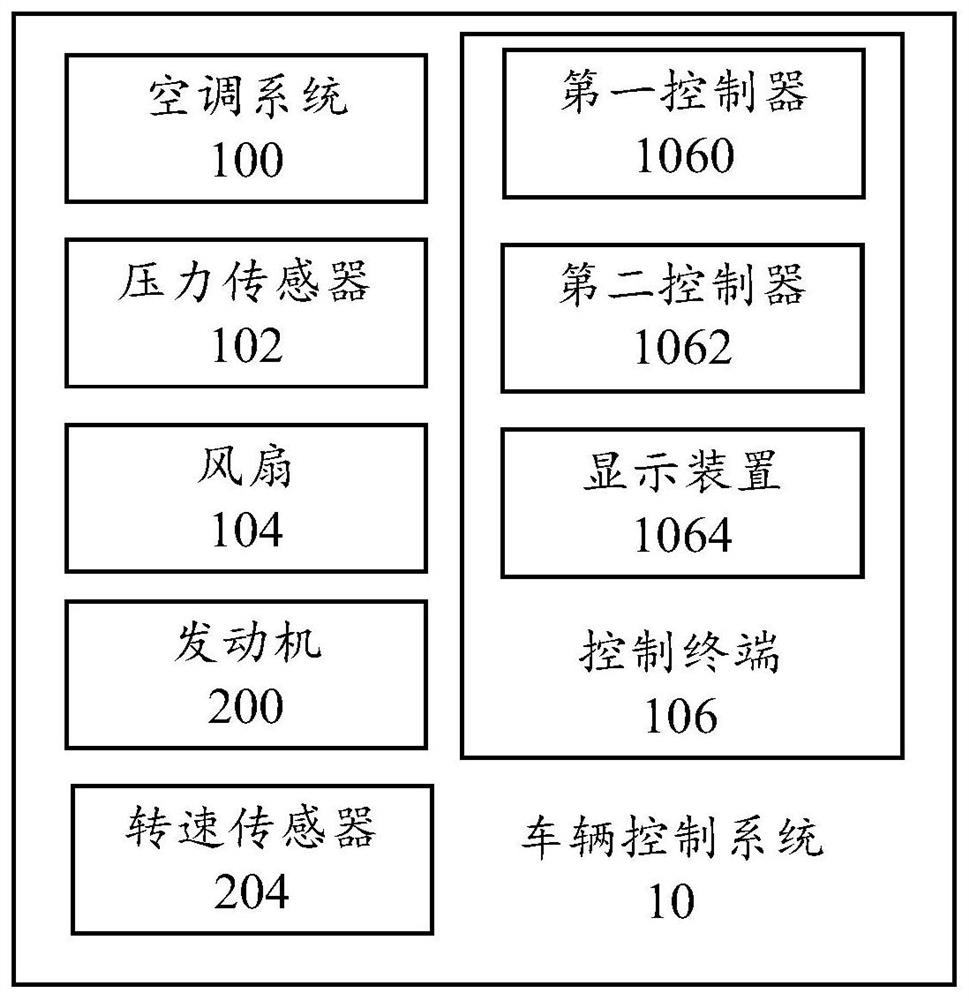
[0035] Such as figure 1 As shown, the vehicle control system 10 according to an embodiment of th...


PUM


Abstract

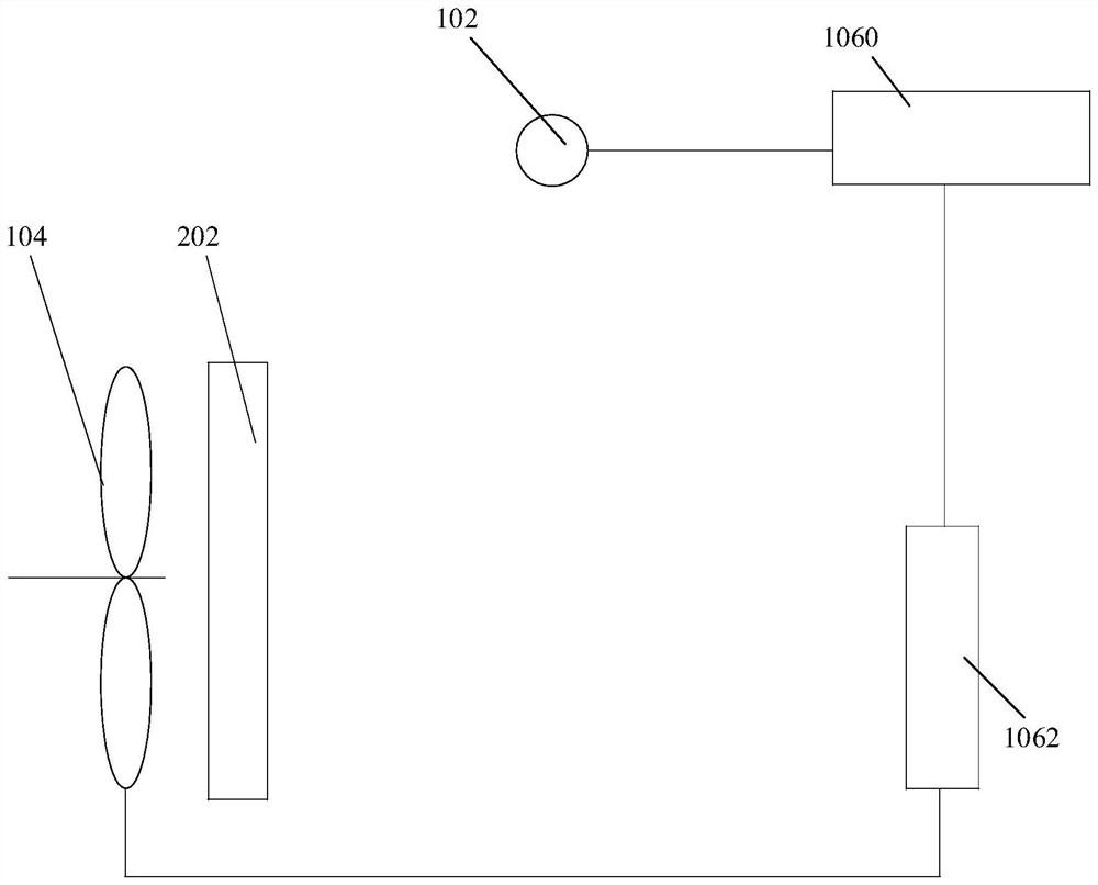
The present invention proposes a vehicle control system, vehicle and control method, wherein the vehicle control system includes: an engine; a speed sensor used to detect the engine speed; an air conditioning system; a pressure sensor set on the air conditioning system to detect The real-time pressure in the system; the fan is connected with the engine, and the fan is driven by the engine, and the fan is used to dissipate heat for the air conditioning system; the control terminal is electrically connected with the speed sensor, the pressure sensor and the fan, and the control terminal is used to control the real-time pressure through The engine controls the operation of the fan. Through the technical solution of the invention, the fan speed can be flexibly and automatically adjusted through the engine according to the actual situation of the air conditioning system, thereby reducing energy consumption and saving energy under the premise of ensuring the heat dissipation effect of the fan.

Description

technical field [0001] The present invention relates to the technical field of vehicles, in particular, to a vehicle control system, a vehicle and a control method. Background technique [0002] The air-conditioning condenser of engineering vehicles mostly dissipates heat through the fan of the engine. When the air conditioner is turned on at idle speed, the condenser’s heat dissipation capacity is poor, resulting in high pressure on the air-conditioning system, which easily damages the compressor. Specifically, at idle speed, through condensation The wind speed in front of the condenser is small, and the heat dissipation of the condenser is poor, which will lead to an increase in the pressure of the air conditioning system. In response to this situation, the existing engineering vehicles have opened the air conditioner idle speed boost function, that is, when the air conditioner is turned on at idle speed, the speed of the engine fan is increased, thereby improving the heat...

Claims


Application Information

Patent Timeline
Patent Type & Authority Patents(China)
IPC IPC(8): F02D29/04F02B63/06F02D31/00B60H1/32
CPCB60H1/3208B60H2001/325B60H2001/3266F02B63/06F02D29/04F02D31/001Y02T10/88
Inventor 罗能武王波涛石伟
Owner SANY SPECIAL PURPOSE VEHICLE CO LTD
Why Eureka
Eureka Blog
Learn More