an air compressor

A technology of air compressor and body, applied in the field of air compressor, can solve problems such as unstable commutation, difficult maintenance, and instability, and achieve the effects of saving space and parts, flexible commutation, and smooth operation

Active Publication Date: 2021-08-06
江苏爱利达机械有限公司
View PDF0 Cites 0 Cited by
  • Summary
  • Abstract
  • Description
  • Claims
  • Application Information

AI Technical Summary

Problems solved by technology

[0002] With the large-scale application of large-scale mechanical equipment, the use of hydraulic drive technology in the field of air compressor application technology is becoming more and more mature. The traditional air compressor uses a crank connecting rod mechanism to realize the reciprocating movement of the piston in the cylinder and then compress the air. The output pulse of the air compressor of this method is large, unstable, and it is easy to get stuck under severe working conditions. In addition, most of the reversing valves that realize the reciprocating motion of the piston in the current hydraulic air compressors use electromagnetic reversing valves and displacement sensors to match each other. Cooperate with the control of the reversing, the sensor is controlled by the proximity switch, the reversing is unstable and unreliable; the control circuit part of the reversing device is controlled by the circuit board, because the circuit board is a non-standard part, and it is difficult to manufacture and process, and repair after damage It is very difficult; if the existing reversing device is continuously energized for a long time, it is easy to damage small devices and cannot meet the requirements of long-term energization, which also affects production efficiency to a certain extent

Method used


Image

  • an air compressor
  • an air compressor
  • an air compressor

Examples


Embodiment Construction

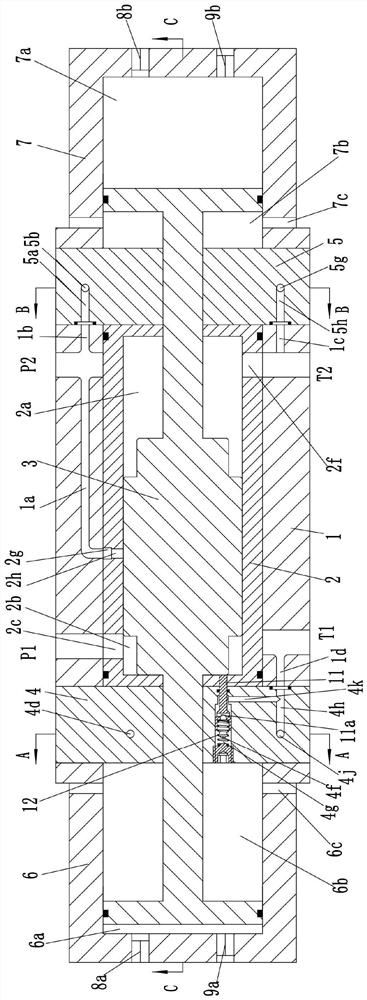
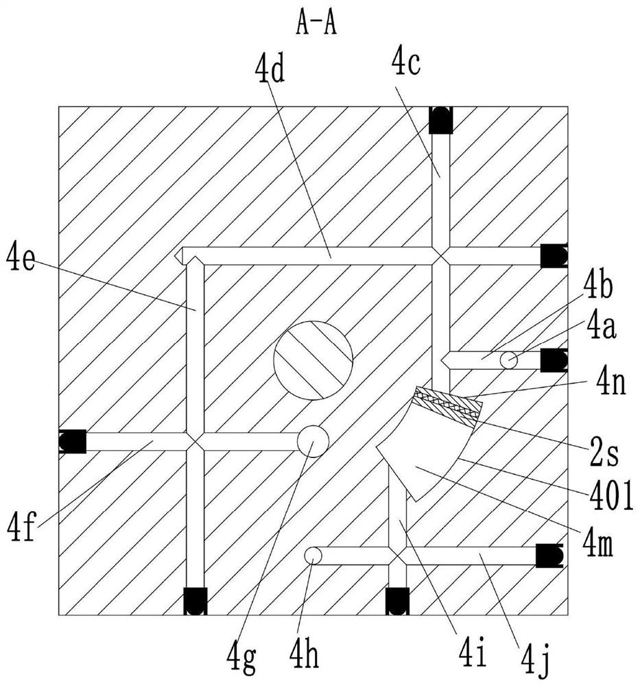
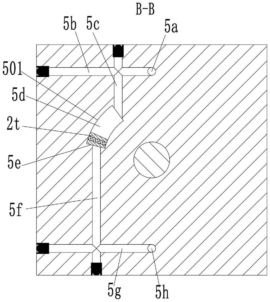
[0034] see Figure 1-15 As shown, an air compressor includes a body 1, and the body 1 is provided with a left and right through installation hole 101; the left end of the body 1 is fixedly installed with a left end cover 4, and the right end is fixedly installed with a right end cover 5; The left side of the left end cover 4 is fixedly installed with a left pump casing 6, and the right side of the right end cover 5 is fixedly installed with a right pump casing 7; the mounting hole 101 is provided with a piston body 3 that moves left and right, and the The left end is provided with the left connecting rod 3a that passes through the left end cover 4 and extends into the left pump casing 6, and the right end is provided with the right connecting rod 3b that passes through the right end cover 5 and extends into the right pump casing 7. The left end of the left connecting rod 3a There is a left piston 3a1 that is slidably connected in the left pump casing 6, and the right end of th...


PUM


Abstract

The invention discloses an air compressor, which comprises a body, and the body is provided with left and right through installation holes; the left end of the body is fixedly installed with a left end cover, and the right end is fixedly installed with a right end cover; the left side of the left end cover is The left pump casing is fixedly installed, and the right pump casing is fixedly installed on the right side of the right end cover; the installation hole is provided with a piston body that moves left and right, and the left end of the piston body is provided with a Inside the left connecting rod, the right end is provided with the right connecting rod that passes through the right end cover and extends into the right pump housing, the left end of the left connecting rod is provided with a left piston, and the right end of the right connecting rod is provided with a right piston; the left pump The left end of the casing is provided with a left-inlet one-way valve and a left-outlet one-way valve, and the right end of the right pump casing is provided with a right-inlet one-way valve and a right-outlet one-way valve; the outer surface of the body is provided with a P1 port, T1 port, P2 port, T2 port; control components are arranged in the installation holes; the air compressor is not only simple in structure, small in size, but also simple in driving mode, without electronic control.

Description

technical field [0001] The invention belongs to the technical field of air compressors, and in particular relates to an air compressor. Background technique [0002] With the large-scale application of large-scale mechanical equipment, the use of hydraulic drive technology in the field of air compressor application technology is becoming more and more mature. The traditional air compressor uses a crank connecting rod mechanism to realize the reciprocating movement of the piston in the cylinder and then compress the air. The output pulse of the air compressor of this method is large, unstable, and it is easy to get stuck under severe working conditions. In addition, most of the reversing valves that realize the reciprocating motion of the piston in the current hydraulic air compressors use electromagnetic reversing valves and displacement sensors to match each other. Cooperate with the control of the reversing, the sensor is controlled by the proximity switch, the reversing i...

Claims


Application Information

Patent Timeline
Patent Type & Authority Patents(China)
IPC IPC(8): F04B35/00F04B49/00
CPCF04B35/008F04B49/002
Inventor 不公告发明人
Owner 江苏爱利达机械有限公司
Why Eureka
Try Eureka