
Phase shifter and base station antenna

A phase shifter and phase shift circuit technology, which is applied to antennas, antenna parts, antenna supports/installation devices, etc., can solve the problems of complex structure of the phase shifter, occupying the back of the antenna, and unfavorable AFU ESC antenna integration, etc. The overall structure is simple and compact, the layout of the whole machine is simplified, and the effect of miniaturized design is achieved.

Pending Publication Date: 2021-08-27
COMBA TELECOM TECH (GUANGZHOU) CO LTD +1
View PDF0 Cites 0 Cited by
  • Summary
  • Abstract
  • Description
  • Claims
  • Application Information

AI Technical Summary

Problems solved by technology

[0003] At present, due to the high passive intermodulation requirements of traditional base station antennas, the phase shifters used are usually dielectric sliding phase shifters. The specific principle is to change the dielectric of the transmission line covered by the dielectric block by driving the dielectric block to slide. Constant, so as to change the phase difference between the feed point and the antenna unit, and then realize the adjustment of the downtilt angle of the antenna, but the structure of this type of phase shifter is generally more complicated, and a large space needs to be reserved in the adjustment stroke of the dielectric block for The dielectric block slides, resulting in a large space on the back of the antenna as a whole, which is not conducive to integration in the AFU electric adjustment antenna

Method used


Image

  • Phase shifter and base station antenna
  • Phase shifter and base station antenna
  • Phase shifter and base station antenna

Examples


Embodiment Construction

[0024] Embodiments of the present invention are described in detail below, examples of which are shown in the drawings, wherein the same or similar reference numerals designate the same or similar elements or elements having the same or similar functions throughout. The embodiments described below by referring to the figures are exemplary only for explaining the present invention and should not be construed as limiting the present invention.

[0025] Those skilled in the art can understand that, unless otherwise stated, the word "comprising" used in the description of the present invention refers to the presence of the features, integers, steps, operations, parts / components and / or components, but does not exclude the presence or Add one or more other features, integers, steps, operations, parts / parts, components and / or groups thereof. It should be understood that when we refer to a part / component as being "connected" to another part / component, it may be directly connected to t...


PUM


Abstract

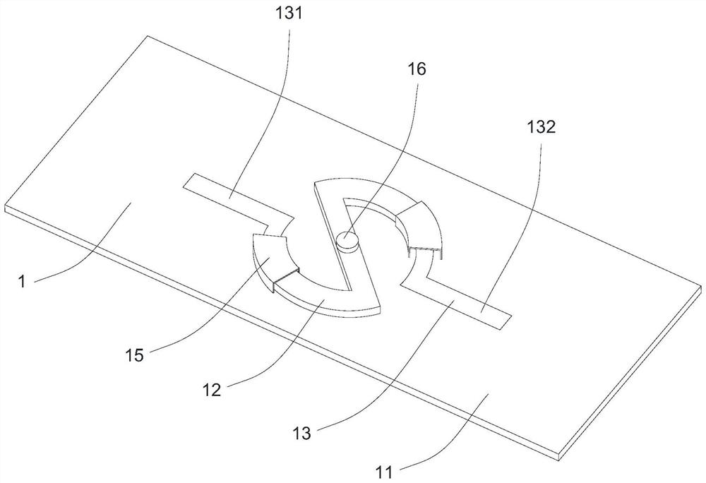
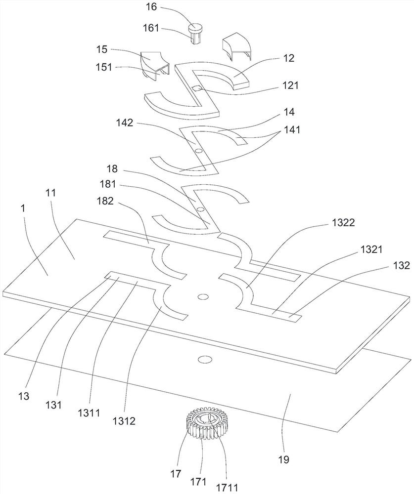
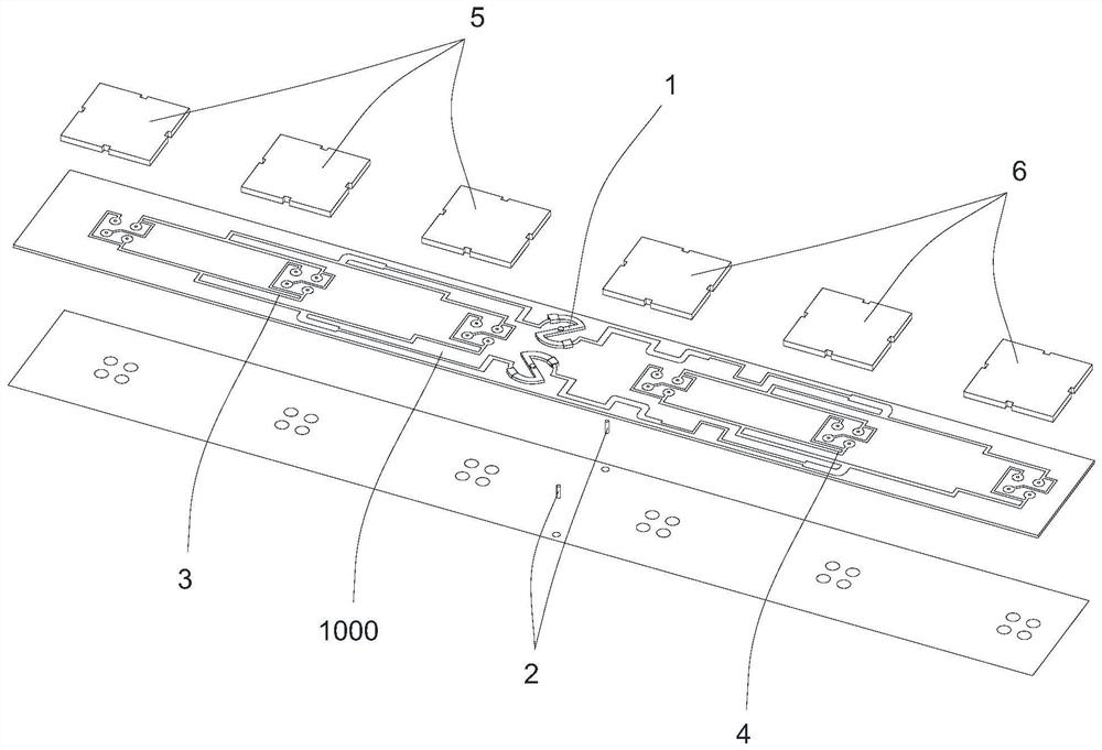
The invention provides a phase shifter and a base station antenna. The phase shifter comprises a substrate, a fixed circuit and a phase shift circuit, wherein the fixed circuit and the phase shift circuit are arranged on the substrate; the fixed circuit comprises an input end and an output end which are separated from each other; the two ends of the phase shift circuit are coupled with the input end and the output end respectively; and the phase shift circuit can rotatably switch the coupling connection position between the phase shift circuit and the input end and the coupling connection position between the phase shift circuit and the output end relative to the substrate. According to the phase shifter provided by the invention, the coupling connection positions between the phase shifting circuit and the input end / the output end can be switched by driving the phase shifting circuit to rotate, so that the circuit length from the input end to the output end is adjusted, and phase adjustment from the input end to the output end is realized; the overall structure is simple and compact, other spaces around the phase shifter are not occupied in the phase shifting adjustment process, and miniaturization design is achieved; and the overall layout of a base station antenna can be simplified when the phase shifter is applied to the base station antenna, and the design integration degree of the antenna is improved so that antenna miniaturization can be achieved.

Description

technical field [0001] The invention relates to the technical field of mobile communication, in particular to a phase shifter and a base station antenna using the phase shifter. Background technique [0002] With the continuous development and updating of 5G communication technology, the application of AFU electric adjustable antenna (5G base station antenna with electric adjustable function integrated dielectric filter) is more and more widely used. In the AFU electronically adjustable antenna, due to the need to integrate a dielectric filter and a shield cover covering the dielectric filter on the back of the antenna, the remaining available space on the back of the antenna is extremely compact, and a complete phase-shifting network needs to be laid out in this space. Therefore, in the AFU electronically adjustable antenna, the requirement for miniaturization of the phase shifter is getting higher and higher. [0003] At present, due to the high passive intermodulation re...

Claims


Application Information

Patent Timeline
Patent Type & Authority Applications(China)
IPC IPC(8): H01P1/18H01Q1/24
CPCH01P1/18H01Q1/246
Inventor 吴旭林焕
Owner COMBA TELECOM TECH (GUANGZHOU) CO LTD
Learn More