
A Harmonic Suppression Metasurface Energy Harvester

An energy harvester and harmonic suppression technology, applied in the direction of antenna, antenna grounding switch structure connection, electrical components, etc., can solve the problems affecting the design of the feeder network, the increase in the design of the antenna array, and the low efficiency, so as to avoid the complexity of the system. and instability increase, solve the high impedance problem, avoid the effect of secondary radiation

Active Publication Date: 2022-02-08
BEIJING UNIV OF POSTS & TELECOMM
View PDF9 Cites 0 Cited by
  • Summary
  • Abstract
  • Description
  • Claims
  • Application Information

AI Technical Summary

Problems solved by technology

In principle, the insertion loss caused by the low-pass filter and the performance impact of the antenna are removed; however, the feed structure of the rectenna uses an open parallel open-circuit stub to suppress harmonics, which is ideal for a single or miniaturized array Effectively, when radio frequency synthesis is used in a large-scale array, the additional space occupied by the stubs on the feeder will affect the design of the feeder network and add additional difficulties to the design of the antenna array
In addition, the traditional patch antenna array is used as the receiving antenna. In order to avoid destructive coupling between units, the antenna array needs to be separated by half a wavelength. Effective solution for miniaturization and high efficiency
At present, most metasurfaces for energy harvesting focus on high-efficiency capture, multi-polarization, and wide incident angles. There is no proposal in the published literature to propose how to solve the harmonic suppression problem of the receiving system on the metasurface.

Method used


Image

  • A Harmonic Suppression Metasurface Energy Harvester
  • A Harmonic Suppression Metasurface Energy Harvester
  • A Harmonic Suppression Metasurface Energy Harvester

Examples


Embodiment 1

[0051] Such as figure 1 , figure 2 As shown, the present embodiment selects 4x4 metal patch units with 16 etched grooves in total to form the receiving surface of the metasurface unit layer of the metasurface energy harvester, and the metal patch of the etched groove passes through a vertical radius of R=0.55mm. Conductive vias connect to the RF output layer, image 3 The feed network on the RF output layer shown integrates the induced current delivered by the vertical conductive vias to a 50ohm load resistor, which is replaced by a 50ohm SMA during testing. Among them, the design method of the feed network on the RF output layer is equivalent to the traditional 1-16 parallel microstrip power division design. A quarter-wavelength transmission line ladder impedance converter is used for impedance transformation, and finally the energy of 16 channels is converged into one output.

[0052] Such as image 3 As shown, the ground layer between the upper metasurface unit layer a...


PUM

PropertyMeasurementUnit
thicknessaaaaaaaaaa
thicknessaaaaaaaaaa
widthaaaaaaaaaa

Abstract

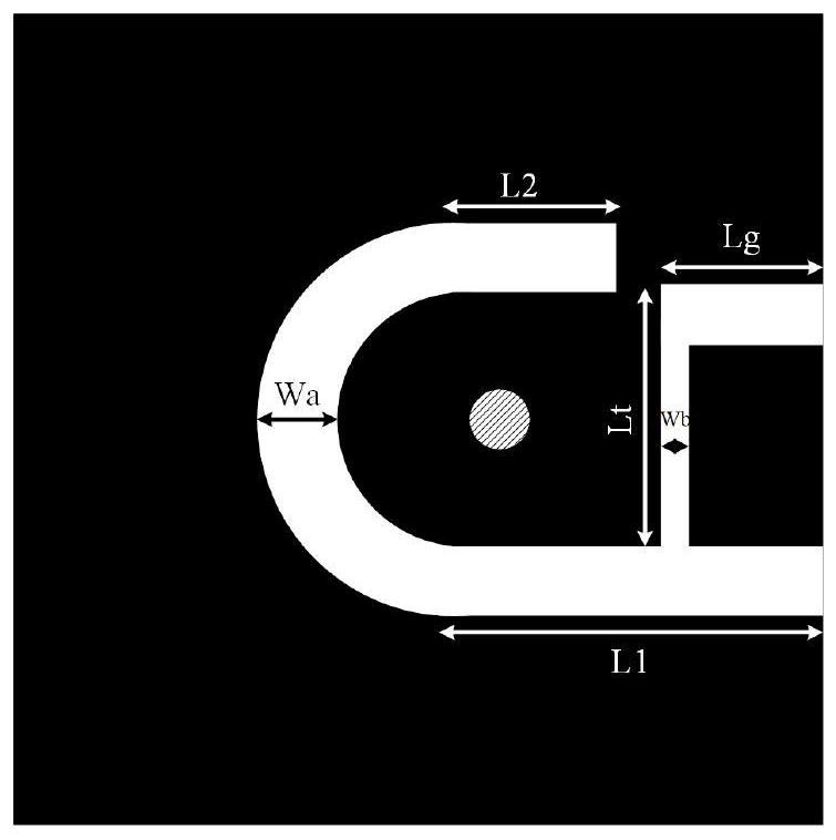
The invention relates to a harmonic suppression metasurface energy collector, which is characterized in that it comprises: a metasurface unit layer, a grounding layer and a radio frequency output layer arranged sequentially from top to bottom; the metasurface unit layer is arranged periodically There are several metasurface units; each of the metasurface units has the same structure, including a dielectric substrate and a metal layer arranged on the dielectric substrate, and the metal layer is etched with an umbrella-shaped groove for realizing incident wave absorption structure and an L-shaped slot structure for realizing harmonic suppression; each said umbrella hook-shaped slot structure is internally provided with a vertical conductive via hole that runs through said metasurface unit layer, and each said metasurface unit passes through each said conductive via The hole passes through the ground layer and is connected to the feed network provided on the radio frequency output layer, and transmits the collected radio frequency energy to the feed network for radio frequency synthesis, so that all the energy is gathered in one place and exported. The invention can be widely used in the field of rectenna design.

Description

technical field [0001] The invention relates to a harmonic suppression metasurface energy collector, which belongs to the field of microwave energy transmission and reception rectifying antennas. Background technique [0002] In the microwave wireless power transfer system (MPT), the rectenna is the key device for converting microwave energy to DC, and it is also an important factor determining the RF-DC energy conversion efficiency of the MPT system. The rectenna is composed of a receiving antenna and a rectifying circuit. The high-order harmonics generated by nonlinear elements such as diodes in the rectifying circuit will be radiated twice by the receiving antenna, which will reduce the efficiency of the rectenna and seriously affect the transmission efficiency of the system. It will cause electromagnetic interference between systems. Therefore, rectifying antenna harmonic suppression technology should focus on solving. On the other hand, in order to avoid destructive c...

Claims


Application Information

Patent Timeline
Patent Type & Authority Patents(China)
IPC IPC(8): H01Q15/00H01Q1/50
CPCH01Q15/0086H01Q1/50
Inventor 张金玲王晨晨朱雄志郑占旗白烁冰李宁贾立飞韩晨
Owner BEIJING UNIV OF POSTS & TELECOMM
Learn More