
A loading and unloading control system based on electromagnetic positioning

A control system and electromagnetic positioning technology, which is applied in the field of compressor control, can solve problems such as unstable oil pressure in the piston chamber, oil leakage, and inability to stabilize the slide valve, so as to avoid frequent loading and unloading, avoid abnormal protection, and facilitate operation Effect

Active Publication Date: 2020-11-24
GREE ELECTRIC APPLIANCES INC
View PDF4 Cites 0 Cited by
  • Summary
  • Abstract
  • Description
  • Claims
  • Application Information

AI Technical Summary

Problems solved by technology

[0004] The existing automatic loading methods of compressors are divided into: stepless loading and unloading and polarized loading and unloading. Among them, due to the sealing problem of the slide valve, there is leakage in the oil circuit that pushes the slide valve to move, making the oil pressure in the piston cavity unstable. Inability to stabilize the slide valve at the predetermined load of the compressor

Method used


Image

  • A loading and unloading control system based on electromagnetic positioning
  • A loading and unloading control system based on electromagnetic positioning
  • A loading and unloading control system based on electromagnetic positioning

Examples


Embodiment 1

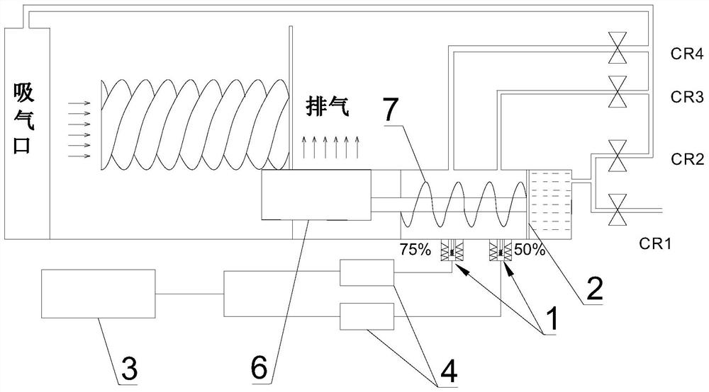
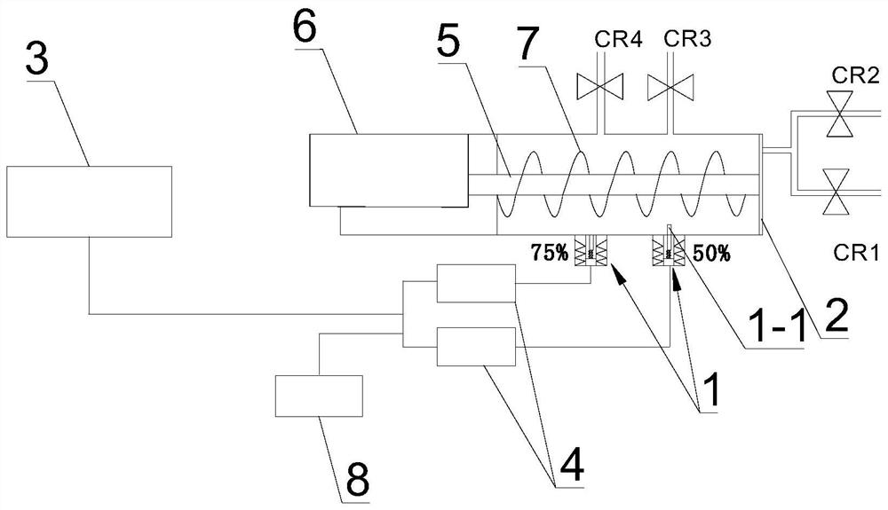
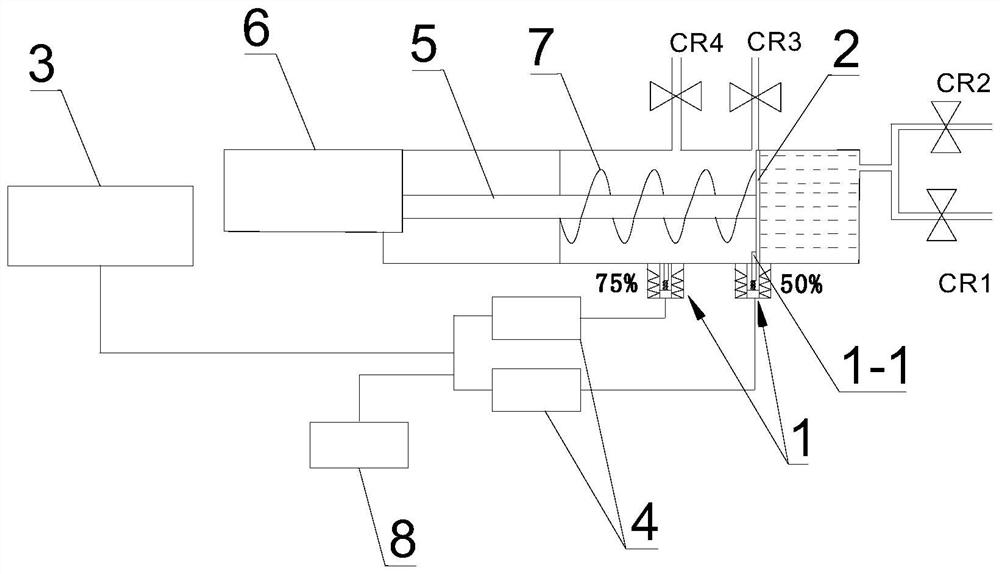
[0027] see Figure 1-6 , the loading and unloading control system based on electromagnetic positioning in this embodiment includes a plurality of electromagnetic limit devices 1 for positioning the piston 2 in the oil cylinder and an electric control module for controlling the positioning work. The limit device 1 includes a limit rod 1-1 and an electromagnetic drive mechanism, the electromagnetic drive mechanism is arranged on the outer wall of the oil cylinder, and is used to drive the limit rod 1-1 to perform telescopic movement toward the inner cavity of the oil cylinder, and the electromagnetic drive mechanism The driving direction of the driving mechanism is perpendicular to the moving direction of the piston 2 in the oil cylinder; in the state of loading and unloading, the limit rod 1-1 is respectively limited on both sides of the piston 2 . Specifically, there are two electromagnetic limiting devices 1, which are respectively set at positions representing 50% and 75% lo...

Embodiment 2

[0039] The difference from Embodiment 1 is that, with the load state 0 as the starting point and 100% as the end point, there are three electromagnetic limit devices 1 in this embodiment, which are respectively arranged on the representative 25%, 50% and 75% of the oil cylinder. position of the load.

Embodiment 3

[0041] Different from Embodiment 1, the load state is 0 as the starting point and 100% as the end point. In this embodiment, the number of electromagnetic limiting devices 1 can also be four, five or even more, depending on the application.


PUM


Abstract

The invention discloses a loading and unloading control system based on electromagnetic locating. The loading and unloading control system comprises electromagnetic limiting devices used for locatinga piston in an oil cylinder and an electric control module used for controlling locating work. Each electromagnetic limiting device comprises a limiting rod and an electromagnetic drive mechanism. Theelectromagnetic drive mechanisms are arranged on the outer side wall of the oil cylinder and used for driving the limiting rods to do telescopic motion towards an inner cavity of the oil cylinder, and the drive direction of the electromagnetic drive mechanisms is perpendicular to the moving direction of the piston in the oil cylinder. The electromagnetic drive mechanisms drive the limiting rods to extend into the oil cylinder to protrude in front of the piston, and the limiting rods limit the piston. In the loading and unloading states, the limiting rods are limited on the two sides of the piston. According to the loading and unloading control system, the piston is precisely located through the electromagnetic locating technology, when a compressor needs to be loaded or unloaded to the set load, the position of the piston can be precisely fixed, and therefore the compressor runs stably, and frequent loading and unloading caused by oil pressure fluctuation are avoided.

Description

technical field [0001] The invention relates to compressor control, in particular to a loading and unloading control system based on electromagnetic positioning. Background technique [0002] With the development of air-conditioning technology, twin-screw compressors have been widely used in the field of commercial air-conditioning. However, the energy adjustment stability of the screw compressor is still a technical problem. The screw compressor cannot automatically load to the target load and continue to load after loading to the target load. These problems will cause the energy adjustment of the compressor to be unstable. The machine cannot run stably under the set load, which affects the reliability of the entire air conditioning unit. [0003] The energy regulation method of the compressor is that the oil in the oil tank flows into the piston cavity through the oil circuit, and the piston in the piston cavity is pushed to move under the action of oil pressure. The pos...

Claims


Application Information

Patent Timeline
Patent Type & Authority Patents(China)
IPC IPC(8): F04B49/06F04B49/12
CPCF04B49/06F04B49/12
Inventor 罗建飞梁相之李永芳李明黄童毅石海勇谢佳东赖继开
Owner GREE ELECTRIC APPLIANCES INC
Learn More