Safety quickly adjusted pipeline butterfly valve

A technology for adjusting pipelines and safety. It is applied in the directions of lift valves, valve details, valve devices, etc. It can solve the problems of single control effect, no tight closure, insufficient sealing of butterfly valves, etc., and achieve the effect of ensuring the sealing effect.

Inactive Publication Date: 2020-05-08
上海伟德船舶有限公司
View PDF0 Cites 3 Cited by
  • Summary
  • Abstract
  • Description
  • Claims
  • Application Information

AI Technical Summary

Problems solved by technology

[0003] In common butterfly valves, the opening and closing of the single plate is used to control the on-off of the fluid, but after a long time of operation, the closure may not be tightly closed, resulting in leakage, and sometimes the electric control butterfly valve is used. After the power is cut off, it cannot be closed effectively, causing casualties; the present invention is applied to a safety quick-adjusting pipeline butterfly valve on ships, which solves the problems of insufficient sealing performance and single control effect of existing butterfly valves, and improves the safety of ships. great effect

Method used


Image

  • Safety quickly adjusted pipeline butterfly valve
  • Safety quickly adjusted pipeline butterfly valve
  • Safety quickly adjusted pipeline butterfly valve

Examples


Embodiment 1

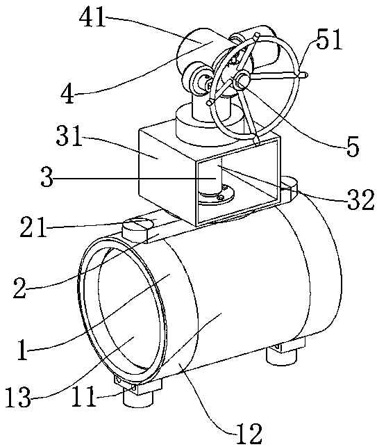
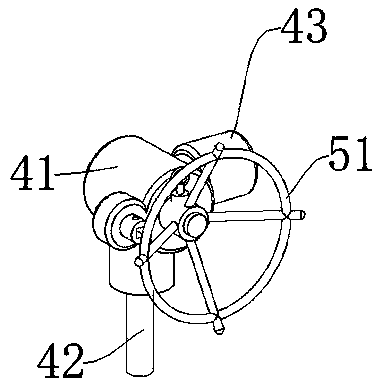
[0045] Such as Figure 1-Figure 7 As shown, the transmission mechanism 2 includes a sealing box 21, a first transmission gear 22, a second transmission gear 23, and a transmission shaft 24. The sealing box 21 is connected to the support frame 31 of the valve body mechanism 1 connecting the cylinder 11 and the support mechanism 3, and the sealing box 21 Inside is provided with a first transmission gear 22, the first transmission gear 22 is connected to the output shaft 42 of the power mechanism 4, the lower end of the first transmission gear 22 is connected to the second transmission gear 23, and the key on the second transmission gear 23 is connected to the transmission shaft 24, the transmission shaft Both ends of 24 are keyed to the third transmission gear 25, the lower end of the third transmission gear 25 is connected to the fourth transmission gear 26, the fourth transmission gear 26 is connected to the rotating shaft 27, and the rotating shaft 27 is connected to the valve...

Embodiment 2

[0048] The difference between this embodiment and embodiment 1 is:

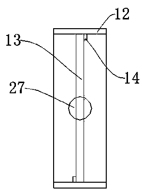
[0049] Such as Figure 8 The transmission mechanism 2 includes a sealed box 21, a first linkage block 211, a linkage plate 212, and a fixed pin 213. Two first linkage blocks 211 are arranged inside the seal box 21, and the first linkage block 211 is connected to the output shaft 42 of the power mechanism 4. , the output end of the first linkage block 211 is keyed to the linkage plate 212, and one end of the linkage plate 212 is connected to the second linkage plate 214, between the first linkage block 211 and the linkage plate 212, and between the linkage plate 212 and the second linkage plate 214 through The fixed pin 213 is connected, the second linkage plate 214 is connected to the rotating shaft 27, the rotating shaft 27 is connected to the valve body plate 13 of the valve body mechanism 1, the output shaft 42 drives the first linkage block 211, and the two first linkage blocks 211 drive the linkage plate...


PUM


Abstract

The invention discloses a safety quickly adjusted pipeline butterfly valve which comprises a valve body mechanism and a supporting mechanism. The supporting mechanism is arranged on the upper side ofthe valve body mechanism. The safety quickly adjusted pipeline butterfly valve further comprises a power mechanism for providing kinetic energy, a manual mechanism for manual control and a transmission mechanism for connecting the valve body mechanism to the power mechanism, wherein the transmission mechanism is connected between the valve body mechanism and the supporting mechanism. The safety quickly adjusted pipeline butterfly valve is reasonable in structure. The safety quickly adjusted pipeline butterfly valve is provided with two valve body outer barrels and a valve body plate to be matched with the transmission mechanism simultaneously, so that the closing effect of the valve body which is closed is guaranteed. The safety quickly adjusted pipeline butterfly valve is simple to operate. The device is provided with a second driving gear, a first driving gear and an electric motor simultaneously, so that a working mode and a working state can be adjusted randomly. By connecting thepower mechanism to the manual mechanism, mistaken operations of someone else by means of the manual mechanism are avoided. When the electric motor cannot be operated, a handheld electric drill can beexternally connected to be connected to a passive fit block to open and close quickly.

Description

technical field [0001] The invention relates to the field of butterfly valves, in particular to a safety quick-adjust pipeline butterfly valve. Background technique [0002] Butterfly valve, also known as flap valve, is a regulating valve with simple structure, which can be used for switching control of low-pressure pipeline medium. of a valve. Valves can be used to control the flow of various types of fluids such as air, water, steam, various corrosive media, mud, oil, liquid metal and radioactive media. It mainly plays the role of cutting and throttling on the pipeline. The opening and closing part of the butterfly valve is a disc-shaped butterfly plate that rotates around its own axis in the valve body to achieve the purpose of opening and closing or adjustment. [0003] In common butterfly valves, the opening and closing of the single plate is used to control the on-off of the fluid, but after a long time of operation, the closure may not be tightly closed, resulting ...

Claims


Application Information

Patent Timeline
Patent Type & Authority Applications(China)
IPC IPC(8): F16K31/05F16K31/53F16K31/60F16K1/22F16K1/32F16K27/02
CPCF16K1/22F16K1/32F16K27/0218F16K31/05F16K31/53F16K31/60
Inventor 赵立生李娜曹庆祝姜巍崯张伯硕
Owner 上海伟德船舶有限公司
Why Eureka
Try Eureka