
Laser receiver mounting equipment

A technology for laser receivers and installation equipment, applied in lighting and heating equipment, instruments, measuring devices, etc., can solve the problems of high temperature of laser receivers, large temperature fluctuation range, affecting measurement accuracy and signal stability, etc., to improve Signal-to-noise ratio, the effect of avoiding excessive noise

Inactive Publication Date: 2020-05-08
湖南森尚仪器有限公司
View PDF10 Cites 0 Cited by
  • Summary
  • Abstract
  • Description
  • Claims
  • Application Information

AI Technical Summary

Problems solved by technology

[0003] At present, the laser gas analyzers on the market, especially the laser receivers in laser gas analyzers used in thermal measurement are generally installed on a special bracket, but because the temperature of the mounting bracket is close to the temperature of the high-temperature measurement gas chamber, The temperature of the laser receiver is high, and the temperature fluctuation range is large. In this case, when the laser receiver receives the laser signal, the signal noise will be large due to temperature change or high temperature, which will seriously affect the measurement accuracy and signal stability.

Method used


Image

  • Laser receiver mounting equipment
  • Laser receiver mounting equipment
  • Laser receiver mounting equipment

Examples


Embodiment Construction

[0023] In order to more clearly illustrate the technical solutions in the embodiments of the present invention or the prior art, the technical solutions in the embodiments of the present invention will be clearly and completely described below in conjunction with the drawings in the embodiments of the present invention. Obviously, the described The embodiments are only some of the embodiments of the present invention, not all of them. Based on the embodiments of the present invention, all other embodiments obtained by persons of ordinary skill in the art without making creative efforts belong to the protection scope of the present invention.

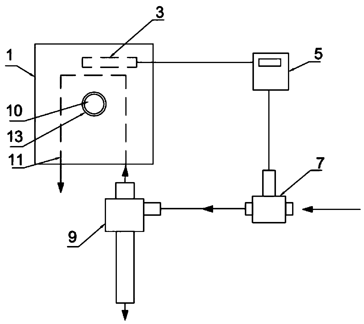
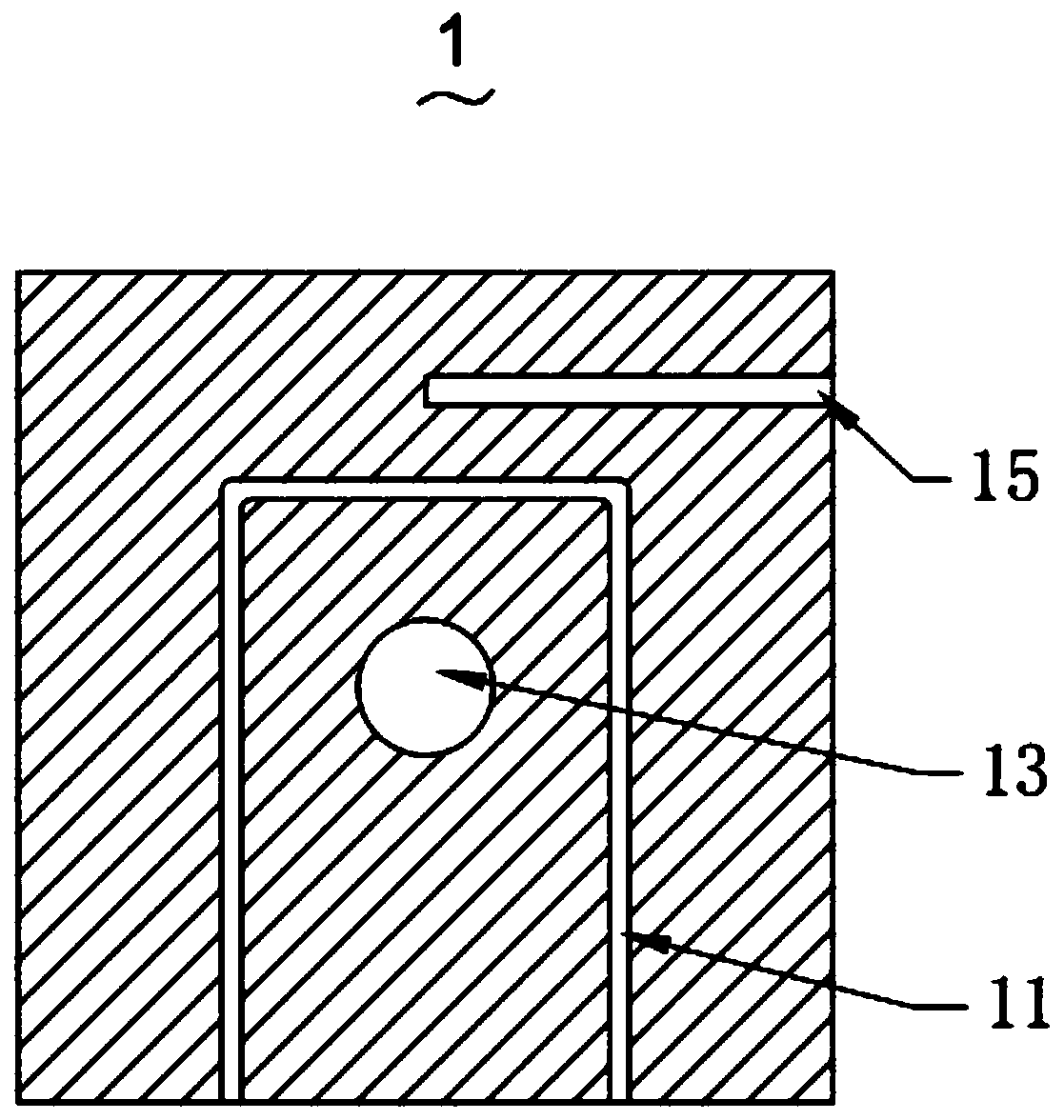
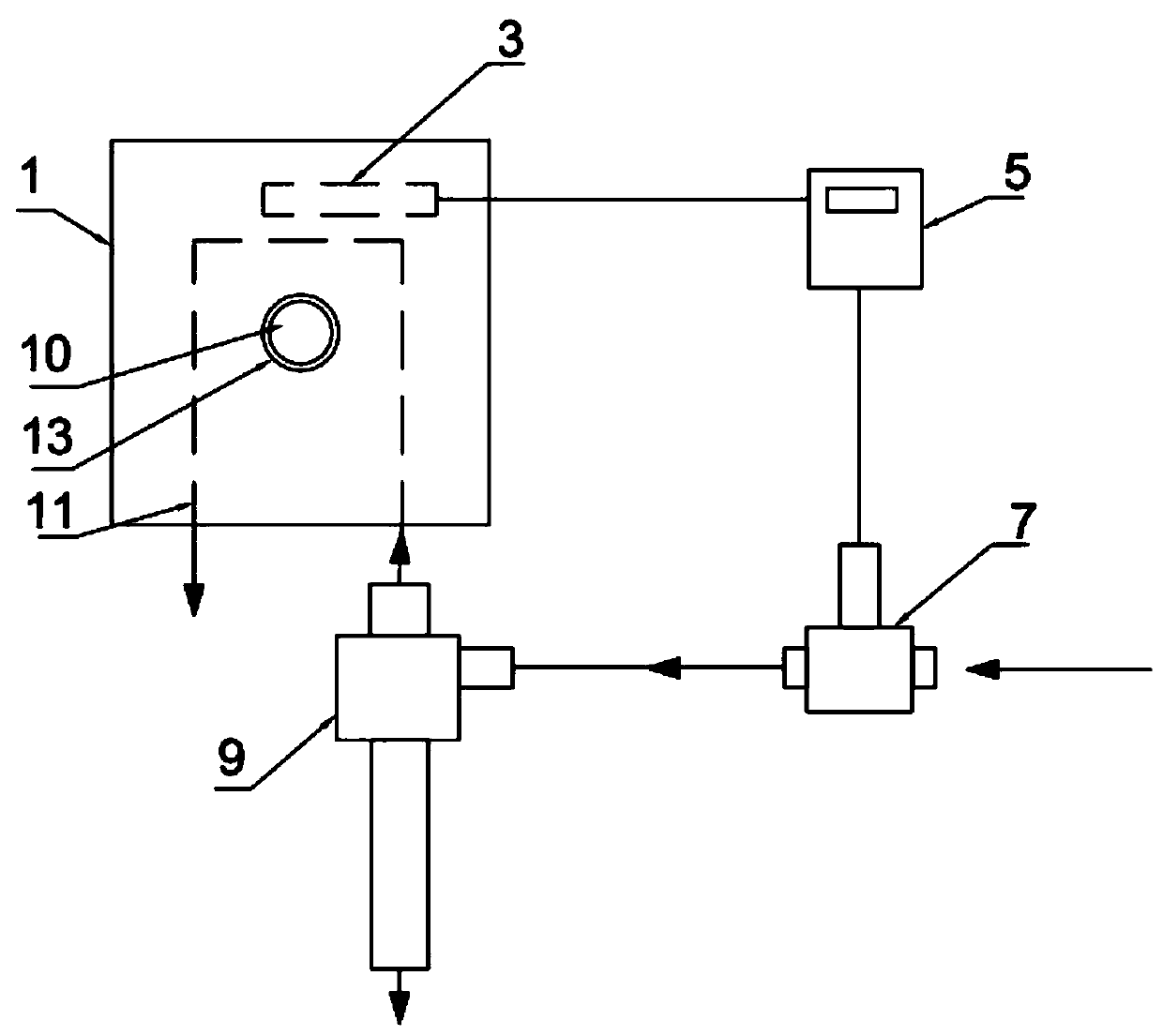
[0024] see figure 1 , is a schematic structural diagram of the installation equipment for the laser receiver 10 provided by the present invention. The installation device for the laser receiver 10 includes an installation body 1 and a temperature detection unit 3 , a temperature control unit 5 , an adjustment unit 7 and a refrigeration ...


PUM


Abstract

The invention discloses laser receiver mounting equipment. The laser receiver mounting equipment comprises a mounting body, a temperature detection unit, a temperature control unit, an adjusting unitand a refrigerating unit; the mounting body is used for mounting a laser receiver; the temperature detection unit is arranged in the mounting body and is used for detecting the temperature of the mounting body; the temperature control unit is used for receiving a signal transmitted by the temperature detection unit; the adjusting unit is used for adjusting the flow of air entering the refrigerating unit so as to control the flow of cold air input into the refrigerating channel by the refrigerating unit. According to the laser receiver mounting equipment disclosed by the invention, the workingtemperature of the laser receiver mounted on the mounting body is reduced by reducing the temperature of the mounting body, therefore, the temperature of the laser receiver is controlled, the situation that the measurement precision is affected due to the fact that the temperature of the laser receiver is too high or the temperature fluctuation is large, and consequently the noise of the laser receiver is too large is avoided, and the signal-to-noise ratio is increased.

Description

technical field [0001] The invention relates to the technical field of laser gas analysis instruments, in particular to a laser receiver installation device. Background technique [0002] Laser gas analyzer is a laser gas analysis system based on semiconductor laser absorption spectroscopy (DLAS: Diode Laser Absorption Spectroscopy) technology, which obtains the concentration of gas by analyzing the selective absorption of laser by gas to achieve the purpose of analysis and measurement. [0003] At present, the laser gas analyzers on the market, especially the laser receivers in laser gas analyzers used in thermal measurement are generally installed on a special bracket, but because the temperature of the mounting bracket is close to the temperature of the high-temperature measurement gas chamber, As a result, the temperature of the laser receiver is high, and the temperature fluctuation range is large. In this case, when the laser receiver receives the laser signal, the sig...

Claims


Application Information

Patent Timeline
IPC IPC(8): G01N21/31G01N21/01F25B9/04
CPCG01N21/31G01N21/01F25B9/04G01N2021/0112
Inventor 郭伟刘胜涛
Owner 湖南森尚仪器有限公司
Learn More