
Integral pump

A composite pump, pump body technology, applied in the direction of pumps, pump devices, pump components, etc., can solve the problems of easy failure, short service life, small liquid flow, etc., to achieve low failure rate, long service life, and low noise. Effect

Inactive Publication Date: 2003-06-11
INST OF METAL RESEARCH - CHINESE ACAD OF SCI
View PDF0 Cites 0 Cited by
  • Summary
  • Abstract
  • Description
  • Claims
  • Application Information

AI Technical Summary

Problems solved by technology

When in use, the motor drives the centrifugal impeller to realize the transportation of liquid. The main disadvantages of the pump are high speed, high noise, small liquid flow, easy failure and short service life.

Method used


Image

  • Integral pump
  • Integral pump
  • Integral pump

Examples


Embodiment Construction

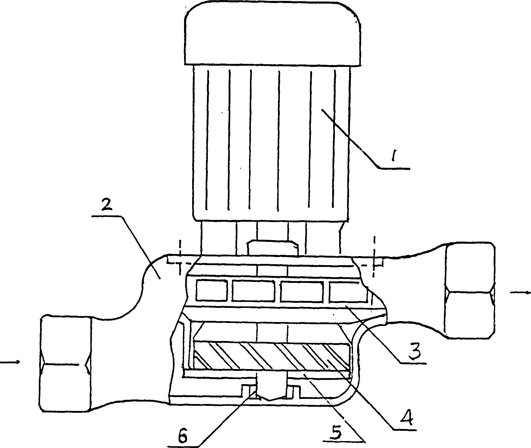
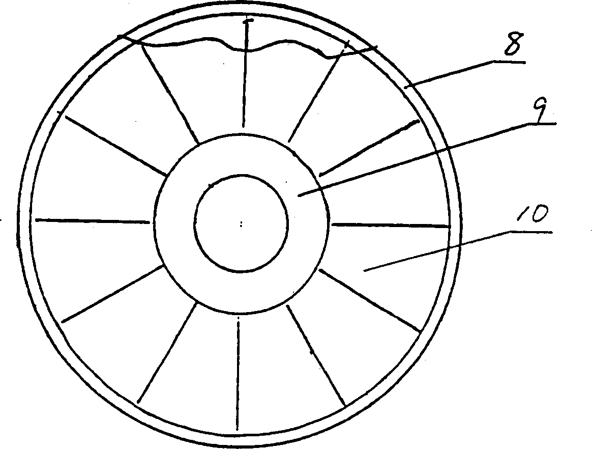
[0011] The centrifugal impeller 3 of the present invention is a radial centrifugal water wheel; the rotary impeller 4 is such as figure 2 Shown is a wheel body with rotating blades 10 between the outer ring 8 and the hub 9; the racer disk 5 is a sheet-shaped disk with a plurality of through holes 7, and the outer circle is a threaded body.

[0012] During installation, the centrifugal impeller and rotary impeller that penetrate into the pump body on the motor shaft in turn are fixed and connected with keys or screws. The vanishing disc is fixed on the bottom of the pump body by threads or screws to maintain a small gap with the rotary impeller. Wear-resistant bearings Installed on the inner bottom surface of the pump body to support the motor shaft.

[0013] When in use, the motor drives the centrifugal impeller and the rotary impeller to rotate, and the liquid is conveyed through the rotary impeller and the centrifugal impeller; the anti-rotation disc fixed on the pump body is u...


PUM


Abstract

An integrated pump, an improved water pump, features that the long motor shaft fixed to pump body passes sequentically through centrifugal blade wheel, rotary vane wheel and despin disk. Its advantages include compact structure, low rotation speed and noise, high flow and long service life.

Description

Technical field [0001] The invention belongs to the improvement of the water pump. Background technique [0002] The common water pump is usually composed of a pump body and a centrifugal impeller in the pump body. When in use, the motor drives the centrifugal impeller to achieve liquid transportation. The main disadvantages of the pump are high speed, high noise, low liquid flow, easy failure, and short service life. Summary of the invention [0003] The purpose of the present invention is to provide a composite water pump that can make the pump work less noise and large liquid flow in response to the above-mentioned disadvantages. [0004] The technical point of the present invention is: a composite pump with a motor and a pump body, characterized in that: the long shaft of the motor 1 fixed on the pump body 2 is sequentially fitted with a centrifugal impeller 3, a rotary impeller 4, Race disc 5, the tail end of the long shaft of the motor 1 extending into the pump body 2 is f...

Claims


Application Information

Patent Timeline
Patent Type & Authority Patents(China)
IPC IPC(8): F04D1/08F04D13/06F04D25/06F04D29/66
Inventor 常殿林吴维
Owner INST OF METAL RESEARCH - CHINESE ACAD OF SCI
Learn More