PID control method of fuel cell system
A technology of a fuel cell system and control method, which is applied in the direction of fuel cells, circuits, electrical components, etc., and can solve the problems of slow response speed and large error of PID controllers
- Summary
- Abstract
- Description
- Claims
- Application Information
AI Technical Summary
Problems solved by technology
Method used
Image

Examples
Embodiment Construction
[0033] Embodiments of the present invention are described in detail below, examples of which are shown in the drawings, wherein the same or similar reference numerals designate the same or similar elements or elements having the same or similar functions throughout. The embodiments described below by referring to the accompanying drawings are exemplary and are intended to explain the present invention, but cannot be construed as limitations to the present invention. Based on the embodiments in the present invention, those of ordinary skill in the art have no creative work All other embodiments obtained under the premise all belong to the protection scope of the present invention.
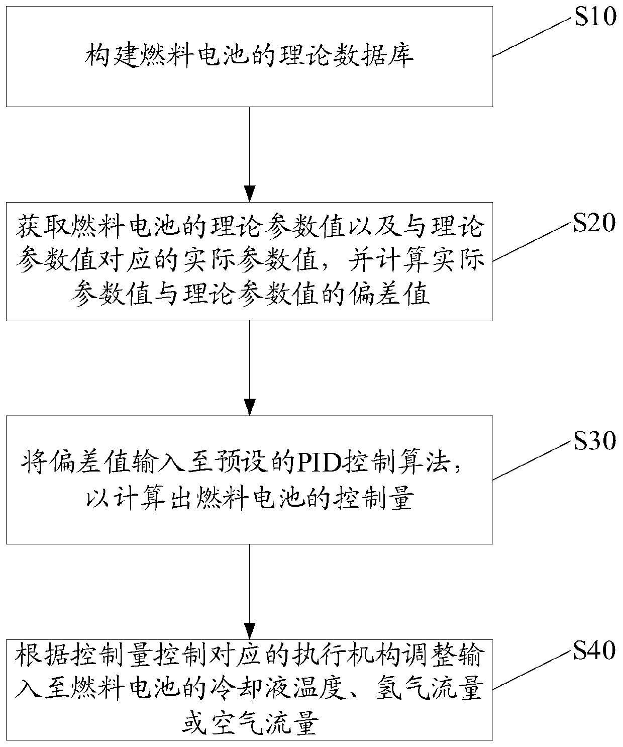
[0034] The present invention proposes a PID control method for a fuel cell system, wherein the fuel cell system includes a fuel cell stack, a hydrogen supply system for supplying hydrogen to the fuel cell stack, an air supply system for supplying air to the fuel cell stack, and Cooling systems for c...
PUM
 Abstract
Description
Claims
Application Information