A kind of embedded micro-pump driven heat dissipation structure and heat dissipation method

A heat dissipation structure and heat dissipation method technology, which is applied to electric vehicles, generators/motors, and modification through conduction heat transfer, etc., can solve the problems of high chip surface temperature and poor heat dissipation effect, and achieve enhanced heat exchange efficiency and enhanced The effect of heat exchange power

Active Publication Date: 2020-11-03
PEKING UNIV
View PDF4 Cites 0 Cited by
  • Summary
  • Abstract
  • Description
  • Claims
  • Application Information

AI Technical Summary

Problems solved by technology

[0004] Therefore, the embodiment of the present invention provides a built-in micropump-driven heat dissipation structure and heat dissipation method to solve the problem in the prior art that using a common heat sink for convective heat dissipation, the temperature of the chip surface is still high, and the heat dissipation effect is not good.

Method used


Image

  • A kind of embedded micro-pump driven heat dissipation structure and heat dissipation method
  • A kind of embedded micro-pump driven heat dissipation structure and heat dissipation method
  • A kind of embedded micro-pump driven heat dissipation structure and heat dissipation method

Examples


Embodiment 1

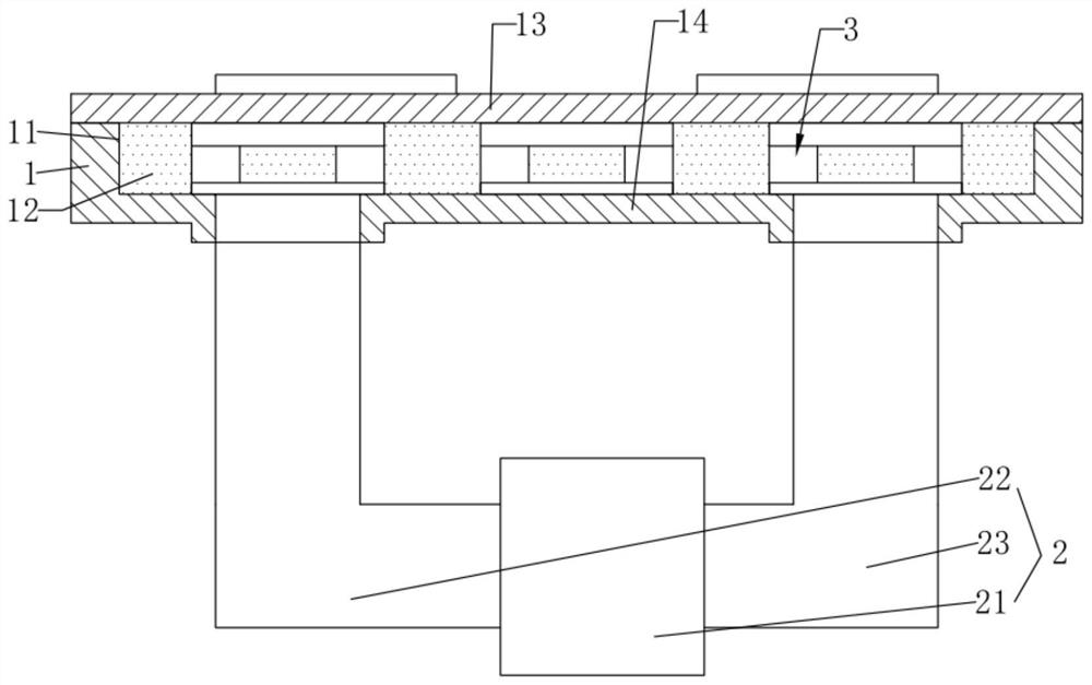
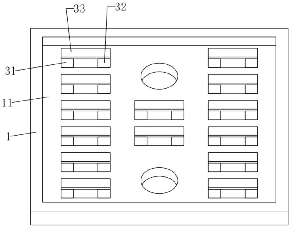
[0044] An embedded micropump-driven cooling structure, such as Figure 1 to Figure 5 As shown, a heat dissipation housing 1 is included, and a heat dissipation chamber 11 is formed inside the heat dissipation housing 1; a heat dissipation working medium 12 is filled in the heat dissipation chamber 11; The heat dissipation working medium 12 is continuously extracted and continuously input into the embedded micro-channel forced cooling module 2 . During use, the heat dissipation housing 1 is installed and fixed on one side of the device to be dissipated, and the heat of the device to be dissipated passes through the heat dissipation housing 1 through heat transfer, and exchanges heat with the internal heat dissipation working medium 12 . The internal heat dissipation working medium 12 continuously flows out of the heat dissipation housing 1 and continuously flows into the heat dissipation housing 1 to achieve continuous heat exchange, thereby achieving a cooling effect.

[0045...

Embodiment 2

[0111] A heat dissipation method based on an embedded micropump 21 driven heat dissipation structure, comprising the following heat dissipation steps:

[0112] S1, start the micropump 21, and the internal heat dissipation working medium 12 circulates to dissipate heat;

[0113] S2. Detect the surface temperature of the device to be dissipated, and select heat recovery or forced heat dissipation.

[0114] In step S2, comprising the following steps:

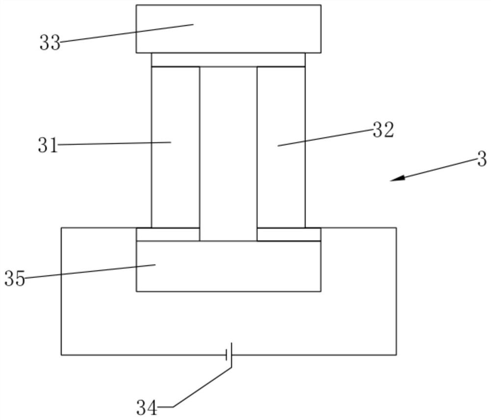
[0115] S21. When the surface temperature of the device to be dissipated is within the heat dissipation range of the embedded micro-channel forced cooling module 2, the first semiconductor column 31 and the second semiconductor column 32 supply power to the outside.

[0116] S22. When the surface temperature of the device to be dissipated is higher than the heat dissipation range of the embedded micro-channel forced cooling module 2, supply power to the first semiconductor column 31 and the second semiconductor column 32 to carry o...


PUM


Abstract

The embodiment of the invention discloses an embedded micro-pump driving type heat dissipation structure and a heat dissipation method, and relates to the technical field of heat dissipation devices.The key points of the technical scheme are that the structure comprises a heat dissipation shell, and a heat dissipation cavity is formed in the inner side of the heat dissipation shell; the heat dissipation cavity is filled with a heat dissipation working medium; an embedded micro-channel forced cooling module for continuously pumping out and inputting a heat dissipation working medium in the heat dissipation cavity is arranged at the outer side of the heat dissipation shell; and a thermoelectric conversion module for transferring heat at one side of the heat dissipation shell to the other side of the heat dissipation shell is arranged at the inner side of the heat dissipation cavity. The heat dissipation method comprises the following heat dissipation steps: S1, starting a micro-pump, wherein the internal heat dissipation working medium circularly flows to dissipate heat; S2, detecting the surface temperature of the to-be-cooled device, and selecting heat recycling or forced cooling.The problems that in the prior art, a common radiator is used for convection heat dissipation, the temperature of the surface of a chip is still very high, and the heat dissipation effect is poor aresolved.

Description

technical field [0001] Embodiments of the present invention relate to the technical field of heat dissipation devices, and in particular to an embedded micropump-driven heat dissipation structure and heat dissipation method. Background technique [0002] Heat dissipation devices are generally used to dissipate heat from electrical components and equipment, and the heat dissipation methods include conduction heat dissipation, convection heat dissipation, and the like. Conduction heat dissipation refers to a heat dissipation method in which the heat of the body is directly transferred to a lower temperature object in contact with it; convection heat dissipation refers to a heat dissipation method in which heat is exchanged through gas flow. [0003] Existing components and chips will emit a lot of heat during use. At the same time, existing chips are becoming more and more integrated. Therefore, in the actual use of existing chips, under a small area, A large amount of heat i...

Claims


Application Information

Patent Timeline
Patent Type & Authority Patents(China)
IPC IPC(8): H05K7/20H02N11/00H02J7/32H02J7/00
CPCH02J7/0031H02J7/32H02N11/002H05K7/20H05K7/2039
Inventor 王振宇余汇宇任庆宝崔一帆
Owner PEKING UNIV
Why Eureka
Try Eureka