A production control system and method for a filter rod suction resistance stabilizing device
A technology for stabilizing devices and filter rods, applied in the fields of e-liquid filter elements, applications, tobacco, etc., can solve problems such as low production efficiency, difficulty in meeting high-quality and high-efficiency production requirements, lack of intelligence and automation functions, etc., to achieve Improvement of productivity and processing quality
- Summary
- Abstract
- Description
- Claims
- Application Information
AI Technical Summary
Problems solved by technology
Method used
Image
Examples
Embodiment 1
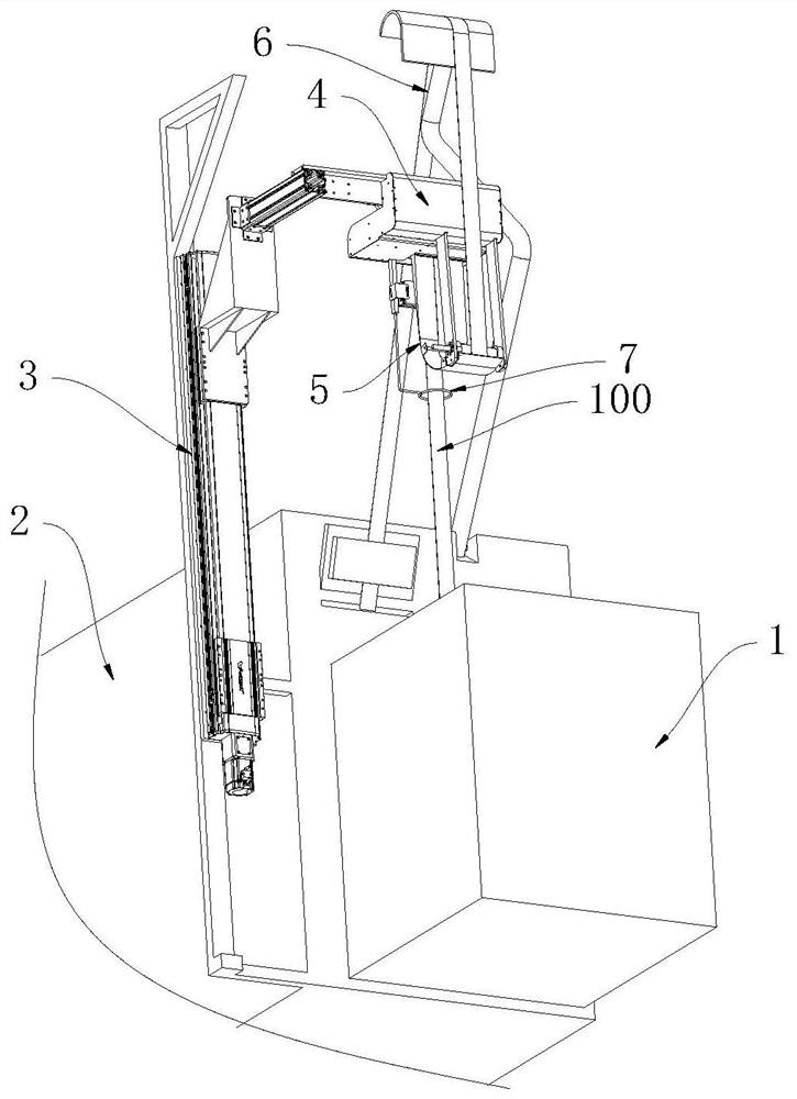
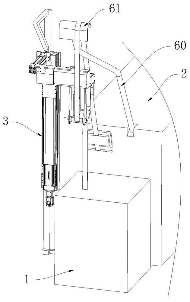
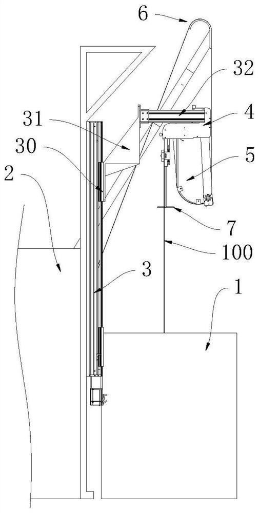
[0030] This embodiment proposes a production control system for a filter rod suction resistance stabilization device, which combines Figure 1 to Figure 4 , Figure 12 , Figures 18 to 20 As shown in the figure, the filter rod suction resistance stabilization device is arranged between a wire bundle feeding device 1 and a filter rod forming device 2, and the filter rod suction resistance stabilization device includes a lifting device 3, a wire bundle pulling device 4, a wire The tow buffer device 5 and the tow support frame 6, the tow feeding device 1 is used to output the tow 100, the filter rod forming device 2 is used to process the tow 100 into a filter rod, the lifting device 3 is installed on the base of the filter rod forming device 2, the tow pulling device 4 is installed on the lifting end of the lifting device 3 and is located above the tow feeding device 1, the tow buffer The device 5 includes a tension sensor 53, and the tow pulling device 4 is used to draw the t...
Embodiment 2
[0055] This embodiment proposes a filter rod suction resistance stabilization device, which combines Figure 1 to Figure 7 As shown, the filter rod suction resistance stabilization device is arranged between a strand feeding device 1 and a filter rod forming device 2, and the filter rod suction resistance stabilization device includes:
[0056] A lifting device 3 is installed on the base of the filter rod forming device 2, and the lifting device 3 is used to perform the lifting action;
[0057] A tow pulling device 4 is installed on the lifting end of the lifting device 3 and is located above the tow feeding device 1 , and the tow pulling device 4 is used for the output of the wire tow feeding device 1 . The tow exerts a pulling force, thereby pulling the tow 100 outward;
[0058] The tow buffer device 5 includes an arc-shaped wire storage groove 50 extending downward from the bottom of the wire tow pulling device 4, and at least one buffer lever 51 is fixed on the inner side...
Embodiment 3
[0075] This embodiment proposes a tow pulling device, which combines Figure 8 to Figure 11 As shown, the tow pulling device 4 includes a pulling bracket 40, and the pulling bracket 40 is provided with a driving roller 41, a driven roller 42 and a traction driving mechanism 43 for driving the driving roller 41 to rotate, The driving roller 41 and the driven roller 42 are arranged side by side and are pressed against each other. A tow guide ring 7 is fixed under the traction bracket 40 , and the tow 100 passes through the tow guide ring 7 from bottom to top. , the tow 100 passes through between the driving roller 41 and the driven roller 42 from the top. When the driving roller 41 rotates, the driving roller 41 and the driven roller 42 cooperate with each other. Then, the tow 100 is pulled, and then the tow 100 is transported below the driving roller 41 and the driven roller 42 .
[0076] In the above structure, through the close cooperation between the driving roller 41 and t...
PUM
 Abstract
Description
Claims
Application Information
 - R&D
- Intellectual Property
- Life Sciences
- Materials
- Tech Scout
- Unparalleled Data Quality
- Higher Quality Content
- 60% Fewer Hallucinations
Browse by: Latest US Patents, China's latest patents, Technical Efficacy Thesaurus, Application Domain, Technology Topic, Popular Technical Reports.
© 2025 PatSnap. All rights reserved.Legal|Privacy policy|Modern Slavery Act Transparency Statement|Sitemap|About US| Contact US: help@patsnap.com


