Textile size storage device convenient to use

A storage device and slurry technology, applied in transportation and packaging, mixers with rotating containers, dissolution, etc., can solve problems affecting users' normal use of slurry, slurry condensation, and lack of stirring structures in storage tanks, etc., to achieve Rich in functions, improved slurry quality, and easy to clean up

Inactive Publication Date: 2020-05-12
唐红英
View PDF9 Cites 0 Cited by
  • Summary
  • Abstract
  • Description
  • Claims
  • Application Information

AI Technical Summary

Problems solved by technology

[0004] However, due to the lack of a corresponding stirring structure in the storage tank, the slurry is easy to condense due to uneven heating, which affects the normal use of the slurry by the user

Method used


Image

  • Textile size storage device convenient to use
  • Textile size storage device convenient to use
  • Textile size storage device convenient to use

Examples


Embodiment 1

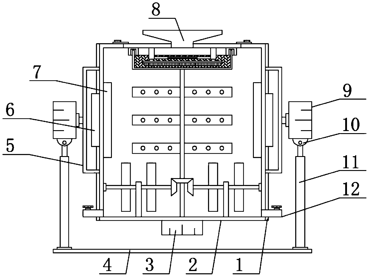
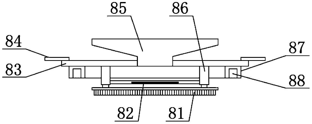
[0024] see Figure 1-Figure 4 , the present invention provides a technical solution: an easy-to-use textile slurry storage device, comprising a storage tank 2, the two sides of the storage tank 2 are welded with discharge pipes 12, and the two sides of the storage tank 2 are also provided with Microwave heater 6 is arranged, and the use of microwave heater 6 is prior art, and the top of storage tank 2 is provided with unloading mechanism 8, and unloading mechanism 8 comprises support top plate 83, and the upper surface middle part of support top plate 83 is provided with unloading hopper 85, the two ends of the support top plate 83 are welded with a fixed plate 84 corresponding to the storage tank 2, and one end of the fixed plate 84 is fixedly connected with the storage tank 2 by screws;

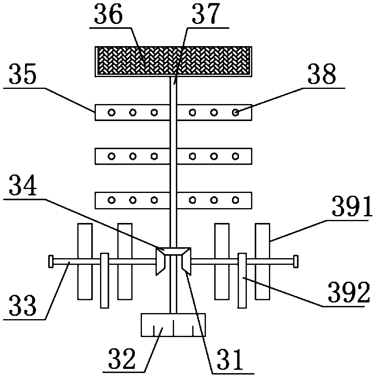
[0025] The bottom end of the storage tank 2 is provided with a stirring mechanism 3, the stirring mechanism 3 includes a second drive motor 32, the output end of the second drive motor 32 i...

Embodiment 2

[0031] On the basis of Embodiment 1, in order to make the use of the filter screen cover 36 more reliable, in this embodiment, preferably, the lower surface of the supporting top plate 83 is provided with a limit slide rail 87, and the bottom end of the limit slide rail 87 is provided with a The limit chute 88 corresponding to the filter screen cover 36 is used to limit the filter screen cover 36 by the limit slide rail 87;

[0032] In order to make the use of the limit slide rail 87 more reliable, in this embodiment, preferably, the top of the limit slide rail 87 is fixedly connected to the support top plate 83 by welding, and the bottom end of the electric telescopic rod 86 is provided with a heating plate 82, The heating plate 82 is a cuboid structure;

[0033] In order to make the use of the heating plate 82 more reliable, in this embodiment, preferably, the two ends of the heating plate 82 are fixedly connected with the electric telescopic rod 86 by welding, and the insid...


PUM


Abstract

The invention discloses a textile size storage device convenient to use. The invention belongs to the technical field of textiles, storage tank, discharge pipes are arranged on the two sides of the storage tank; microwave heaters are further arranged on the two sides of the storage tank; a discharging mechanism is arranged at the top end of the storage tank and comprises a supporting top plate; adischarging hopper is arranged in the middle of the upper surface of the supporting top plate; fixing plates corresponding to the storage tank are arranged at the two ends of the supporting top plate;a stirring mechanism is arranged at the bottom end of the storage tank and comprises a second driving motor, wherein a transmission shaft is arranged at the output end of the second driving motor, afilter screen cover is arranged at the top end of the transmission shaft, and stirring members are arranged on the two sides of the transmission shaft. The slurry stirring device is simple in structure and convenient to use, has a good stirring function, can fully stir slurry in the storage tank, and effectively prevents the slurry from being condensed due to uneven heating, so that normal use ofthe slurry by a user is guaranteed.

Description

technical field [0001] The invention belongs to the technical field of textiles, and in particular relates to an easy-to-use textile slurry storage device. Background technique [0002] Chinese patent (publication number is CN209302302U) discloses a storage tank for textile pulp, including a tank body, a storage tank is provided in the tank body, a feed port connected to the storage tank is opened at the top of the tank body, and a There is a fixed base, on which there is a vibrating frame, a square filter screen located below the feed inlet is installed on the top of the vibrating frame, and a baffle is fixed on the bottom of the square filter screen; a semi-circular platform is fixed on the bottom of the tank body, and a semi-circular platform is opened inside the semi-circular platform. The slag discharge port is connected with a slag discharge pipeline at the bottom of the square filter screen, and a switch valve is arranged in the slag discharge pipeline, and the slag d...

Claims


Application Information

Patent Timeline
Patent Type & Authority Applications(China)
IPC IPC(8): B01F13/10B01F9/12B01F15/00B01F15/06B01F29/83
CPCB01F29/83B01F33/8305B01F35/42B01F35/94
Inventor 唐红英
Owner 唐红英
Why Eureka
Try Eureka