A kind of air-blown ceramic original tire stripper

A stripper and ceramic technology, applied in the field of strippers, can solve the problems of easy fatigue, affecting work efficiency, and troublesome operation.

Active Publication Date: 2021-05-14
DEHUA COUNTY LIDE HOUSEHOLD ARTICLE CO LTD
View PDF7 Cites 0 Cited by
  • Summary
  • Abstract
  • Description
  • Claims
  • Application Information

AI Technical Summary

Problems solved by technology

[0005] In order to overcome the shortcomings of holding an air gun to blow the air into the gap between the original tire and the mold, the air gun needs to be moved back and forth continuously, the operation is troublesome, and after a long time, people are easily tired and affect the work efficiency. The technical problem of the present invention is: to provide a An air-blown ceramic tire stripper that can replace manual blowing of air into the gap between the original tire and the mold. It is easy to operate and does not easily affect work efficiency due to fatigue.

Method used


Image

  • A kind of air-blown ceramic original tire stripper
  • A kind of air-blown ceramic original tire stripper
  • A kind of air-blown ceramic original tire stripper

Examples


Embodiment 1

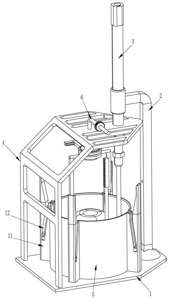
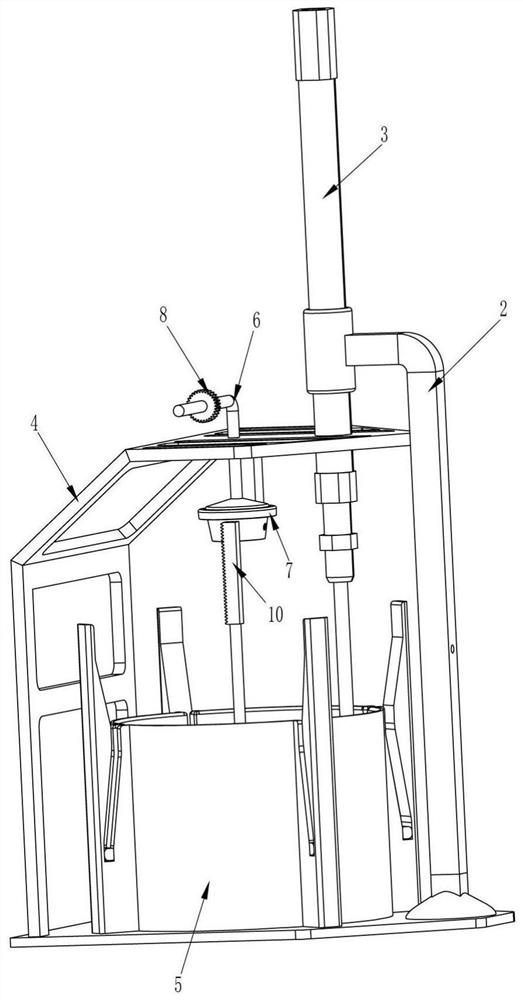
[0023] see Figure 1-Figure 3 , a kind of air-blown ceramic tire stripper, including a base 1, a support rod 2, a driving mechanism, a frame 4, a placement box 5, an air blowing mechanism and a placement frame 9, and the left side of the top of the base 1 is fixedly connected with an organic Frame 4, an air blowing mechanism is provided in the middle of the top of the frame 4, a storage box 5 is fixed in the middle of the top of the base 1, a sliding frame 9 is provided in the storage box 5, and a support rod 2 is fixed in the middle of the top right side of the base 1 , A drive mechanism is provided between the left end of the support rod 2 and the placement frame 9.

[0024] The driving mechanism includes a cylinder 3 and a rack 10. The left end of the support rod 2 is fixedly connected with the cylinder 3. The cylinder 3 is vertically arranged. The bottom of the cylinder 3 runs through the right side of the top of the frame 4. The right side is fixedly connected, and the b...

Embodiment 2

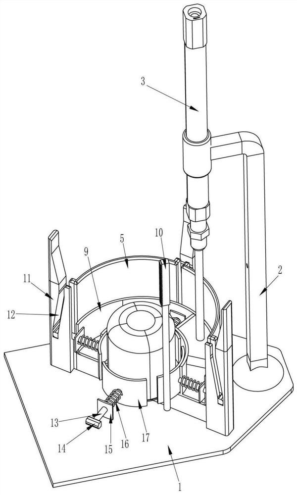
[0030] see Figure 1-Figure 3 , the present embodiment is with respect to embodiment 1, and main difference is that in the present embodiment, also comprise limiting block 11, slide bar 13, first slide block 14, baffle plate 15, first spring 16 and splint 17, place box 5 The outer surface is circumferentially evenly spaced and fixedly connected to the limit block 11, the bottom of the limit block 11 is fixedly connected with the top of the base 1, the upper part of the limit block 11 is provided with a chute 12, and the chute 12 communicates with the inside of the placement box 5, and the placement frame 9 The sliding type evenly spaced in the inner circumferential direction is provided with a slide bar 13, the slide bar 13 corresponds to the limit block 11, the inner end of the slide bar 13 is fixedly connected with a splint 17 which can limit the mold, and the outer end of the slide bar 13 runs through the placement frame 9 1. The placement box 5 and the limit block 11 are l...

Embodiment 3

[0033] see figure 1 , Figure 4 and Figure 5 , the main difference between this embodiment and embodiment 1 and embodiment 2 is that in this embodiment, it also includes a connecting ring 18, an L-shaped hollow push rod 19, a push block 20, a second spring 21, a clamping rod 22, a second Three springs 23, backguy 24, jet pipe 25, windshield block 26, pulley 27, the second slide block 28 and the 4th spring 29, high-pressure air pipe 6 outer lower parts are connected with connection ring 18 in rotation type, connection ring 18 left and right sides All are connected with air jet pipe 25, and the lower part of high-pressure air pipe 6 is evenly spaced circumferentially with air outlet 271, and air outlet 271 cooperates with connecting ring 18. The windshield block 26 cooperates with the air outlet 271 and the jet pipe 25. The top of the windshield block 26 is connected with a fourth spring 29, and the tail end of the fourth spring 29 is fixedly connected with a second slide blo...


PUM


Abstract

The invention relates to a demoulding device, in particular to an air-blowing ceramic original tire demoulding device. The technical problem is how to design a kind of air-blown ceramic original tire stripper that can replace manual airflow blowing into the gap between the original tire and the mould, is easy to operate, and is not easy to be tired and affect work efficiency. An air-blown ceramic original tire stripper, including a base, a frame is fixedly connected to the edge of one side of the base, a storage box is installed on the side of the base close to the frame, and a support rod is installed on the side of the base away from the frame . The invention puts the original tire and the mold into the middle of the placement frame, and then connects the high-pressure air pipe to the air pump, shortens the telescopic rod of the starting cylinder, so that the rack drives the switch to open, and the high-pressure air pipe sprays the airflow into the gap between the original tire and the mould. There is no need to hold the air gun to move the original tire from the mold continuously. It is easy to operate, not easy to be tired, and has high work efficiency.

Description

technical field [0001] The invention relates to a demoulding device, in particular to an air-blowing ceramic original tire demoulding device. Background technique [0002] Ceramic mold: In 1877, the United States used clay as a binder to make ceramic grinding wheels, which marked the birth of ceramic molds. In 1930, ceramic molds began to choose the organization number. In 1970, ceramic binder cubic boron nitride grinding wheels appeared. 20 After the 1980s, foreign ceramic molds developed rapidly and their technical level was high. my country's ceramic molds have been developed since the 1950s, and ceramic molds have always occupied a dominant position in the overall composition of abrasive tools. The output shows a downward trend, but it still accounts for a relatively large proportion of the total molds. Ceramic molds are indispensable production materials in ceramic production. The production of ceramic molds is an important part of ceramic production, and the original t...

Claims


Application Information

Patent Timeline
Patent Type & Authority Patents(China)
IPC IPC(8): B24D18/00B28B13/06
CPCB24D18/0009B28B13/065
Inventor 刘美苹
Owner DEHUA COUNTY LIDE HOUSEHOLD ARTICLE CO LTD
Why Eureka
Try Eureka