Nuclear power station personnel airlock
A technology for personnel gates and nuclear power plants, applied in the field of nuclear power, can solve the problems of poor passing capacity, failure to meet the design standards of personnel gates, and inability to provide sufficient radiation shielding capabilities, etc., to achieve the effect of meeting the passing requirements
- Summary
- Abstract
- Description
- Claims
- Application Information
AI Technical Summary
Problems solved by technology
Method used
Image

Examples
Embodiment Construction
[0047] In order to have a clearer understanding of the technical features, purposes and effects of the present invention, the specific implementation manners of the present invention will now be described in detail with reference to the accompanying drawings.
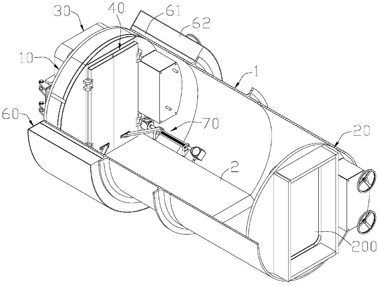
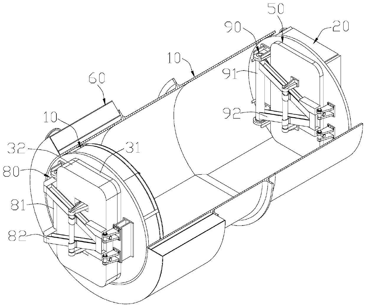
[0048] Such as figure 1 , 2 As shown, the personnel gate of a nuclear power plant according to an embodiment of the present invention includes a cylinder body 1 , a first end plate assembly 10 , a second end plate assembly 20 , a first airtight door 30 , a screen door 40 and a second airtight door 50 .
[0049] In a nuclear power plant, the cylinder 1 is connected to the containment, and its internal space serves as a passage for personnel or equipment to pass in and out of the containment. The barrel 1 may include a first end and a second end opposite to each other, wherein the first end is inserted into the containment vessel, and the second end is located outside the containment vessel.
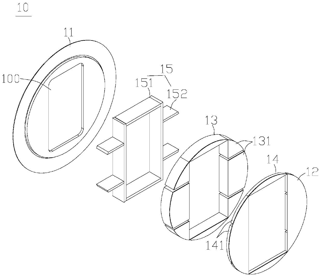
[0050] The first end plate...
PUM
 Abstract
Description
Claims
Application Information