
A low-noise axial flow fan

An axial flow fan and low-noise technology, which is applied in the direction of axial flow pumps, mechanical equipment, machines/engines, etc., can solve the problems of high noise in use and no noise reduction design, etc., and achieve the effect of low noise in use

Active Publication Date: 2021-01-08
浙江欧盾风机有限公司
View PDF6 Cites 0 Cited by
  • Summary
  • Abstract
  • Description
  • Claims
  • Application Information

AI Technical Summary

Problems solved by technology

These two noises will inevitably be generated during the working process of the fan, and the above-mentioned axial flow fan does not have a corresponding noise reduction design, resulting in the use of the axial flow fan with this structure.

Method used


Image

  • A low-noise axial flow fan
  • A low-noise axial flow fan
  • A low-noise axial flow fan

Examples


Embodiment Construction

[0035] The present invention will be described in further detail below in conjunction with the accompanying drawings.

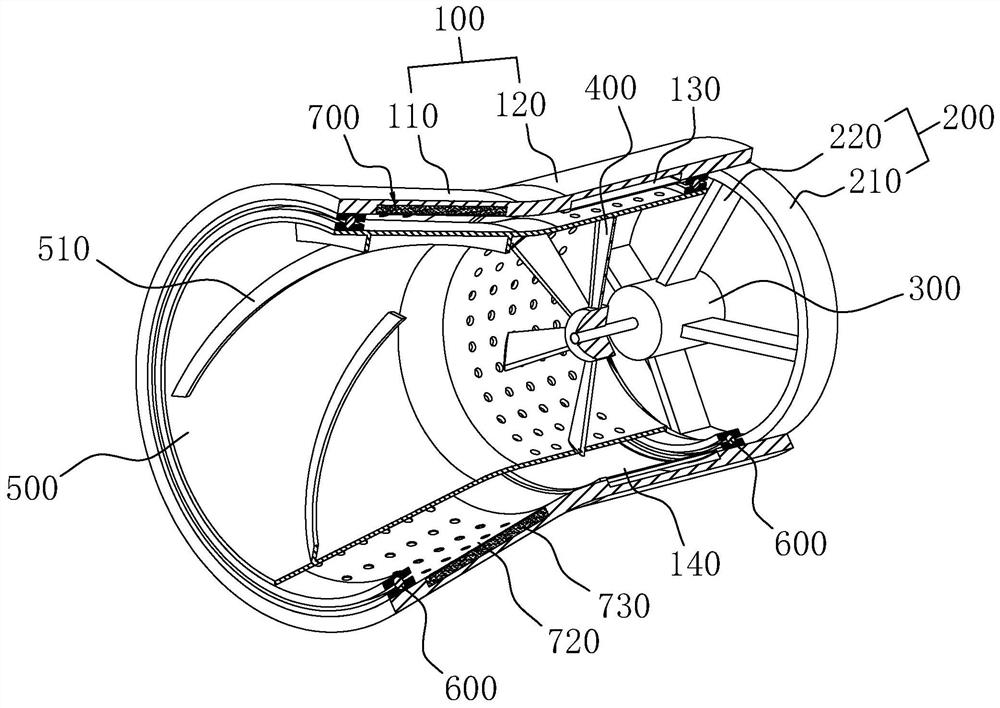
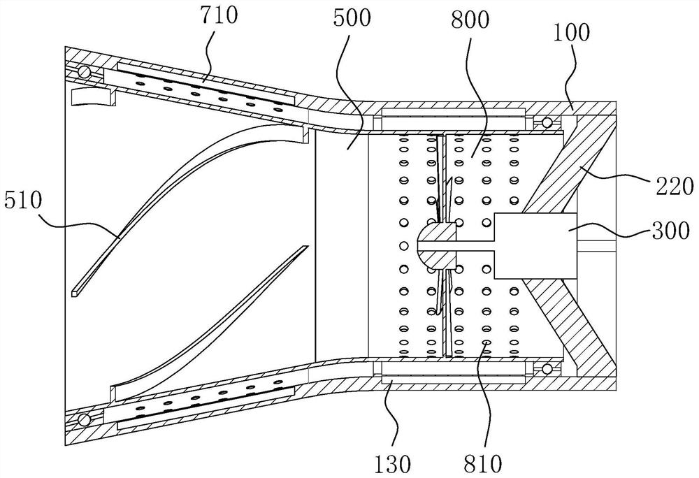
[0036] A low-noise axial flow fan, such as figure 1 As shown, it includes a housing 100, a fixed frame 200, a driving motor 300, a wind wheel 400 and a rotating cylinder 500. The housing 100 is in a cylindrical structure, and it is divided into a straight cylinder part 120 and an expanded cylinder part 110 along the axial direction. The straight cylinder part 120 and the expanded tube part 110 are integrally arranged, wherein the opening at the end of the expanded tube part 110 with a larger diameter is used as an air outlet, and the opening of the straight tube part 120 is used as an air inlet.

[0037] The fixing frame 200 includes a fixing ring 210 and a connecting arm 220 , and the fixing ring 210 is fixed and installed at the air inlet of the straight barrel portion 120 by bolts. There are four connecting arms 220 . combined with figure 2 One end of ...


PUM


Abstract

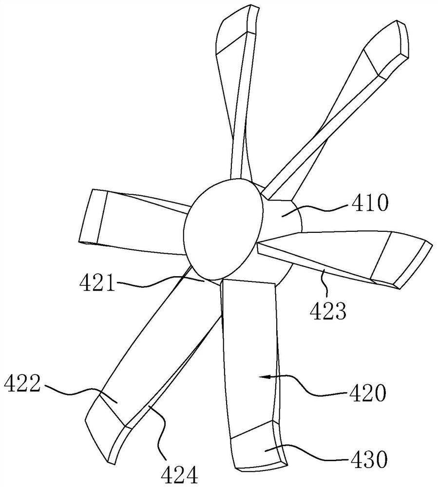
The invention discloses a low-noise axial flow fan. The low-noise axial flow fan comprises a shell, a fixing frame installed on the shell, a driving motor installed on the fixing frame and a wind wheel installed on a rotating shaft of the driving motor, a rotating drum is rotationally connected to the interior of the shell, the rotating drum is located between the wind wheel and the shell, the rotating drum extends to an air inlet from an air outlet of the shell. a plurality of follow-up blades used for driving the rotating drum and the wind wheel to rotate in the same direction are arranged on the inner wall of the rotating drum, the follow-up blades are spirally arranged and located between an impeller and the air outlet of the shell; and at least four blades are arranged on the wind wheel, arc-shaped bent turbulent flow parts are arranged at the blade tips of the blades, and the bending angle of each turbulent flow part is 1 to 3 degrees. According to the low-noise axial flow fan, the rotating drum, a silencing cavity, a sound absorption structure and a specific blade structure are arranged, so that the use noise is low.

Description

technical field [0001] The invention relates to the technical field of axial flow fans, in particular to a low-noise axial flow fan. Background technique [0002] The axial flow fan means that when the impeller rotates, the gas enters the impeller axially from the air inlet, is pushed by the blades on the impeller to increase the energy of the gas, and then flows into the guide vane. The guide vanes change the deflected airflow into axial flow, and at the same time introduce the gas into the diffuser pipe, further convert the kinetic energy of the gas into pressure energy, and finally introduce it into the fan of the working pipeline. [0003] The Chinese patent with the publication number CN108194387A discloses an axial flow fan. The present invention has an outer rotor motor, a fixed frame and an impeller; the fixed frame has an outer ring body; the outer rotor motor is fixedly connected to the center of the fixed frame; The impeller is fixedly connected to the outer roto...

Claims


Application Information

Patent Timeline
Patent Type & Authority Patents(China)
IPC IPC(8): F04D19/00F04D25/08F04D29/32F04D29/38F04D29/66F04D29/52F04D29/54
CPCF04D19/002F04D25/08F04D29/325F04D29/386F04D29/388F04D29/522F04D29/547F04D29/663F04D29/664F04D29/666F04D29/667
Inventor 楼益民郑军祥夏新锋董瑞高
Owner 浙江欧盾风机有限公司
Learn More