Three-dimensional suction cup

A suction cup, three-dimensional technology, applied in the directions of manipulators, chucks, manufacturing tools, etc., can solve the problems of falling suction, destroying the state of fluid rotation, and unstable adsorption, and achieve the effect of improving suction and increasing adsorption.

Active Publication Date: 2017-01-04
ZHEJIANG UNIV
View PDF9 Cites 0 Cited by
  • Summary
  • Abstract
  • Description
  • Claims
  • Application Information

AI Technical Summary

Problems solved by technology

[0003] Mechanical fixtures usually have two or more splints that can be opened and closed. The clamping operation is realized by tightening the splints with force, and there are the following problems: 1. The point contact between the mechanical fixture and the object is easy to cause the problem of stress concentration ; 2. When the object to be grasped is a soft material object, such as tomatoes, cakes, etc., the mechanical fixture is easy to cause damage to the object; 3. There are many parts in the mechanical fixture, which are worn out during use, resulting in daily maintenance, Maintenance work is heavy
This results in no contact between the suction cup and the workpiece. Therefore, the suction cup cannot provide friction to the workpiece in the lateral direction. Without lateral friction, the workpiece cannot follow the suction cup in the lateral direction.
[0007] 2. When the fluid flows through the gap flow channel between the outer edge of the bottom surface of the suction cup and the workpiece, under the action of viscosity, a high pressure distribution higher than the pressure of the peripheral environment will be formed (see Figure 1c ), the high pressure distribution on the outer edge of the bottom surface will not only exert a repelling force on the workpiece below, but also make the low pressure distribution in the cavity move to the high pressure direction, which will lead to the weakening of the suction force
As a result, fluid must be turbulent when flowing through such a flow channel (see Figure 2a and 2b ), which causes a sharp drop in suction and the adsorption becomes unstable
The study found that the pressure distribution on the outer edge of the bottom surface of the suction cup and the low-pressure distribution in the cavity are in a linked relationship, that is to say, the pressure distribution on the outer edge becomes disordered, and the low-pressure distribution in the cavity also becomes disordered, resulting in suction become unstable
Moreover, the rough surface of the workpiece will also increase the flow resistance when the fluid is discharged, and the high pressure distribution formed on the outer edge of the bottom surface higher than the ambient pressure will continue to increase, and the repulsive force acting on the workpiece will increase. Make the low pressure distribution in the cavity move to the high pressure direction
These factors eventually lead to a sharp decrease in suction and become unstable
[0009] 4. When the workpiece is made of soft material, the workpiece deforms under the low pressure in the cavity, causing the center part to sink into the cavity
Parts where local contact occurs cannot discharge fluid, resulting in severe asymmetry in the circumferential direction of fluid discharge and confusion
The turmoil of fluid discharge disrupts the state of fluid rotation in the chamber, resulting in a significant drop in suction
[0010] 5. When adsorbing a three-dimensional object (such as an ellipsoidal object), the force area of ​​the negative pressure formed by the cyclone flow is the cross-sectional area of ​​the cylindrical cavity. The lower end adsorption surface of the sucker disclosed in Patent Publication No. CN3640313 is A plane, so there are certain defects when adsorbing three-dimensional objects

Method used


Image

  • Three-dimensional suction cup
  • Three-dimensional suction cup
  • Three-dimensional suction cup

Examples


Embodiment Construction

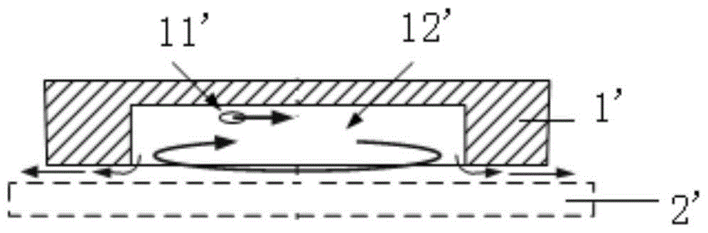
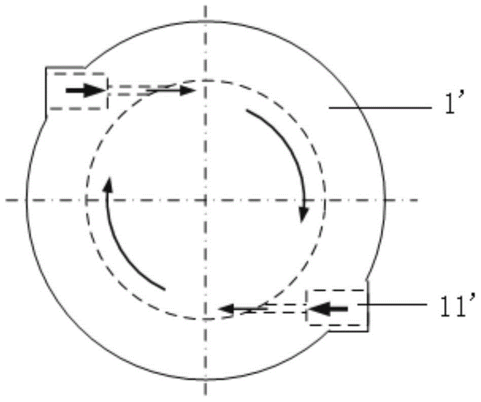
[0031] refer to Figures 4a to 4c with Figure 5b , a three-dimensional suction cup, including a suction cup body, the suction cup body has a cavity 1 with a circular cross section, the cavity has a closed end surface and an open end surface, and the wall surface of the cavity 1 is provided with compressed gas A tangential nozzle 11 connected to the source, the opening end of the cavity 1 is provided with a hollow round table 3 with a small upper part and a larger bottom, the upper opening of the hollow round table 3 coincides with the opening of the opening end face of the cavity 1 ; The inner surface of the hollow circular platform 3 is provided with a helical groove 31, the helical groove 31 forms a fixed exhaust channel, and the helical groove 31 communicates with the inner cavity and the peripheral environment.

[0032]By arranging a hollow circular platform 3 under the suction cup body, the hollow circular platform structure can expand the negative pressure action area....


PUM


Abstract

The invention discloses a three-dimensional sucker. The three-dimensional sucker comprises a sucker body, wherein a cavity with a round cross section is arranged in the sucker body and is provided with a sealed end surface and an opening end surface, a tangential spraying nozzle connected with a compressed air source is arranged on a wall surface of the cavity, a big-end-down hollow circular truncated cone is arranged on the opening end surface of the cavity, and the upper end opening of the hollow circular truncated cone and the opening of the opening end surface of the cavity coincide; a spiral groove is formed in the inner side surface of the hollow circular truncated cone and forms a fixed exhaust passage, and the spiral groove is communicated with the internal cavity and the peripheral environment. The three-dimensional sucker can adsorb a three-dimensional object, and the spiral groove suppresses influences of an irregular shape of the surface of the object on air exhausting. Meanwhile, when the air is exhausted along the spiral groove, the circumferential speed component can be kept to the maximum extent.

Description

technical field [0001] The invention relates to a three-dimensional sucker. Background technique [0002] Taking the production line of fruits, vegetables and bread products in the food industry as an example, in order to sort and pack three-dimensional objects (such as apples, tomatoes, bread, etc.), we need effective grasping tools. At present, the existing three-dimensional object clamping tools in the market mainly include mechanical clamps and rubber vacuum suction cups. [0003] Mechanical fixtures usually have two or more splints that can be opened and closed. The clamping operation is realized by tightening the splints with force, and there are the following problems: 1. The point contact between the mechanical fixture and the object is easy to cause the problem of stress concentration ; 2. When the object to be grasped is a soft material object, such as tomatoes, cakes, etc., the mechanical fixture is easy to cause damage to the object; 3. There are many parts in t...

Claims


Application Information

Patent Timeline
Patent Type & Authority Patents(China)
IPC IPC(8): B25J15/06
Inventor 黎鑫谢欣成张承谦李宁郭之雷杨骥琦
Owner ZHEJIANG UNIV
Why Eureka
Try Eureka