Novel large-view 3D laser camera structure

A technology with a large field of view and a camera, applied in the direction of using optical devices, mechanical devices, mechanical measuring devices, etc., can solve the problems of restricting 3D measurement accuracy, jitter interference, etc., and achieve the effect of ensuring stability and scanning accuracy

Pending Publication Date: 2020-05-12
北京硅谷风尚科技有限公司
View PDF0 Cites 0 Cited by
  • Summary
  • Abstract
  • Description
  • Claims
  • Application Information

AI Technical Summary

Problems solved by technology

[0003] The disadvantage of this method is that not all objects are suitable for moving, and the way of moving the whole camera will be limited by the way of movement. For example, the sliding rail type will have shaking interference, and the handheld type will seriously restrict the accuracy of 3D measurement.

Method used


Image

  • Novel large-view 3D laser camera structure
  • Novel large-view 3D laser camera structure
  • Novel large-view 3D laser camera structure

Examples


Embodiment 1

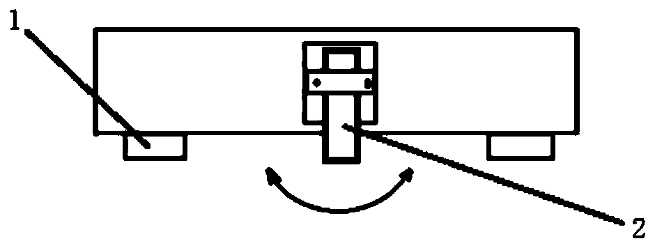
[0020] Such as figure 1 As shown, the present embodiment provides a novel large field of view 3D laser camera structure, including a drive mechanism, a pendulum mechanism 3 and a 3D camera, the 3D camera includes a camera body and a laser 2 arranged at the bottom of the camera body; The driving mechanism is used to drive the pendulum mechanism 3, and the pendulum mechanism 3 is used to drive the laser 2 to swing.

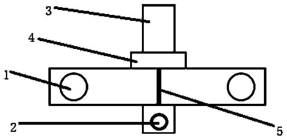
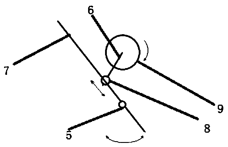
[0021] In this specific example, if Figure 1-3 As shown, the pendulum mechanism 3 includes a connecting rod 6, a swing bar 7 and a slider 8, one end of the connecting rod 6 is connected to the drive mechanism, and the other end of the connecting rod 6 is connected to the slider 8 is connected to the outer wall, and the slider 8 is slidably arranged on the rocking rod 7; the laser 2 is connected to one end of the rocking rod 7. The driving mechanism is a motor 3 , the connecting rod 6 is connected to the power output shaft 9 of the motor 3 , and the connecting rod...


PUM


Abstract

The invention discloses a novel large-view 3D laser camera structure, and relates to the technical field of 3D laser cameras. The main structure comprises a driving mechanism, a pendulum mechanism anda 3D camera, and the 3D camera comprises a camera body and a laser arranged at the bottom of the camera body. The driving mechanism selects a motor, the motor drives the connecting rod to enable a swing rod to swing, so that the laser is driven to swing within a certain angle range, the swing stability of the laser is guaranteed, the scanning interval and the swing range of the laser can be changed by adjusting the rotating angle and the rotating speed of the motor, and the scanning precision is guaranteed.

Description

technical field [0001] The invention relates to the technical field of 3D laser cameras, in particular to a novel large-view 3D laser camera structure. Background technique [0002] In the current high-precision 3D line laser camera, the laser transmitter is fixed on the 3D camera, and the 3D photography process is completed by moving the object or moving the entire camera. [0003] The disadvantage of this method is that not all objects are suitable for moving, and the way of moving the entire camera will be limited by the way of movement. For example, the slide rail type will have shaking interference, and the handheld type will seriously restrict the accuracy of 3D measurement. Contents of the invention [0004] In order to solve the above technical problems, the present invention provides a new large-view 3D laser camera structure, which can freely adjust the scanning width by adjusting the rotation angle, and the whole structure is very stable without affecting the me...

Claims


Application Information

Patent Timeline
Patent Type & Authority Applications(China)
IPC IPC(8): G01B11/24
CPCG01B5/0004G01B11/24
Inventor 杨勋
Owner 北京硅谷风尚科技有限公司
Why Eureka
Try Eureka