
A method and system for on-orbit reconfiguration of on-board fpga

A spaceborne and configuration data technology, applied in response to error generation, program loading/starting, error detection/correction, etc., can solve low reliability, failure to find errors, and inability to realize on-orbit reconstruction of on-orbit reliability of on-board FPGA and other issues to achieve the effect of ensuring correctness, improving data reliability, and highly reliable on-orbit reconstruction

Active Publication Date: 2020-09-18
BEIJING INSTITUTE OF TECHNOLOGYGY
View PDF3 Cites 0 Cited by
  • Summary
  • Abstract
  • Description
  • Claims
  • Application Information

AI Technical Summary

Problems solved by technology

[0003] At present, the usual practice is to burn and solidify the configuration file of the FPGA into the PROM. After curing, the configuration file inside the PROM cannot be changed, resulting in the configuration of the FPGA being completely solidified. If you want to change or upgrade the FPGA program, you need to change or upgrade the The FPGA configuration file is rewritten into the programmable memory FLASH. The verification of the FPGA configuration file is performed before writing the FLASH. After the FPGA configuration file is written into the FLASH, there is no verification process for the FPGA configuration file. Therefore, this reconstruction technology cannot find errors generated in the process of writing to FLASH, and the reliability is low
[0004] For the on-orbit FPGA, it is necessary to ensure high reliability in order to achieve its on-orbit reconfiguration. Therefore, the above-mentioned existing FPGA program reconfiguration technology cannot realize the reliability of the on-orbit reconfiguration of the on-orbit FPGA.

Method used


Image

  • A method and system for on-orbit reconfiguration of on-board fpga

Examples


Embodiment 2

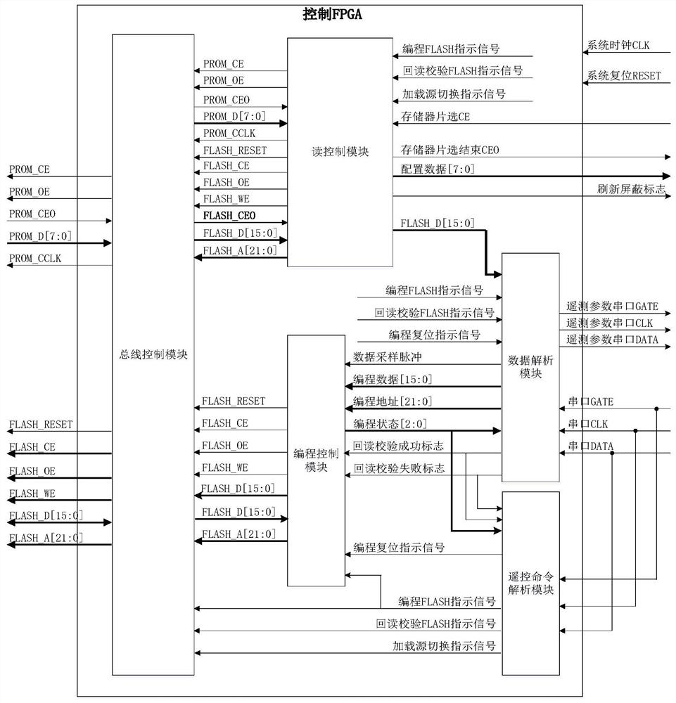
[0100] The embodiment of the present invention also provides an on-orbit reconstruction system, such as figure 1 shown. The control FPGA is composed of a data analysis module, a read control module, a programming control module, a remote control instruction analysis module and a bus control module. The control FPGA performs on-orbit reconstruction for the configuration memory FLASH of the processing FPGA.

[0101] The read control module is connected to the bus control module through the PROM interface and the FLASH interface.

[0102] The PROM interface includes a PROM data interface and a PROM control interface; the FLASH interface includes a FLASH data interface and a FLASH control interface.

[0103] The read control module is connected to the data analysis module through the FLASH data interface.

[0104] The read control module is connected to the load control logic through the memory chip select signal interface.

[0105] The programming control module is connected t...


PUM


Abstract

The invention discloses an on-orbit reconstruction method and system for a satellite-borne FPGA, relates to the technical field of on-orbit reconstruction, and can realize high-reliability on-orbit reconstruction of the FPGA. A control FPGA reads pre-stored configuration data from the PROM by default to process FPGA loading and dynamic refreshing. The control FPGA selects to read pre-stored configuration data from the PROM or the FLASH through a loading source switching instruction sent by the on-board management terminal so as to carry out loading and dynamic refreshing on the processed FPGA.The on-board management terminal sends a FLASH reconstruction instruction to the control FPGA, the control FPGA erases FLASH, then the on-board management terminal starts to send a configuration dataframe to the control FPGA, and the control FPGA analyzes the configuration data frame and extracts configuration data in the configuration data frame. The control FPGA receives the configuration dataframe, and performs dual cyclic redundancy check on the configuration data frame. The control FPGA writes the configuration data into the FLASH after successful erasing, and monitors the FLASH programming state in the writing process. The control FPGA reads back the configuration data written into the FLASH, and performs cyclic redundancy check again.

Description

technical field [0001] The invention relates to the technical field of on-orbit reconfiguration, in particular to an on-orbit reconfiguration method and system of a space-borne FPGA. Background technique [0002] The signal processing system with Field Programmable Gate Array (FPGA Field Programmable Gata Array) as the core is widely used in the electronic systems of space vehicles to realize the main logic functions such as signal processing. In order to realize the loading and starting of the FPGA, its configuration file usually needs to be stored in an external memory (usually implemented by an anti-fuse PROM when on-rail). [0003] At present, the usual practice is to burn and solidify the configuration file of the FPGA into the PROM. After curing, the configuration file inside the PROM cannot be changed, resulting in the configuration of the FPGA being completely solidified. If you want to change or upgrade the FPGA program, you need to change or upgrade the The FPGA c...

Claims


Application Information

Patent Timeline
Patent Type & Authority Patents(China)
IPC IPC(8): G06F9/445G06F11/10
CPCG06F9/4451G06F11/1004
Inventor 侯建刚安文杰崔嵬钟波杨焕全
Owner BEIJING INSTITUTE OF TECHNOLOGYGY
Learn More