Boundary clock window determination method, circuit and terminal equipment and storage medium

A boundary clock and determination method technology, applied in the direction of electrical digital data processing, instruments, etc., can solve the problems of low efficiency, poor adaptability, etc., and achieve the effect of low efficiency, poor adaptability, and simple design

Inactive Publication Date: 2020-05-12
成都三零嘉微电子有限公司
View PDF5 Cites 2 Cited by
  • Summary
  • Abstract
  • Description
  • Claims
  • Application Information

AI Technical Summary

Problems solved by technology

But low efficiency and poor adaptability

Method used


Image

  • Boundary clock window determination method, circuit and terminal equipment and storage medium
  • Boundary clock window determination method, circuit and terminal equipment and storage medium
  • Boundary clock window determination method, circuit and terminal equipment and storage medium

Examples


Embodiment Construction

[0040] In order to have a clearer understanding of the technical features, purposes and effects of the present invention, the specific implementation manners of the present invention will now be described with reference to the accompanying drawings.

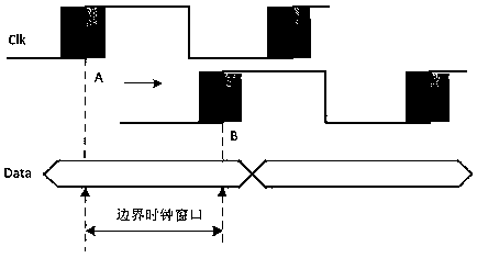
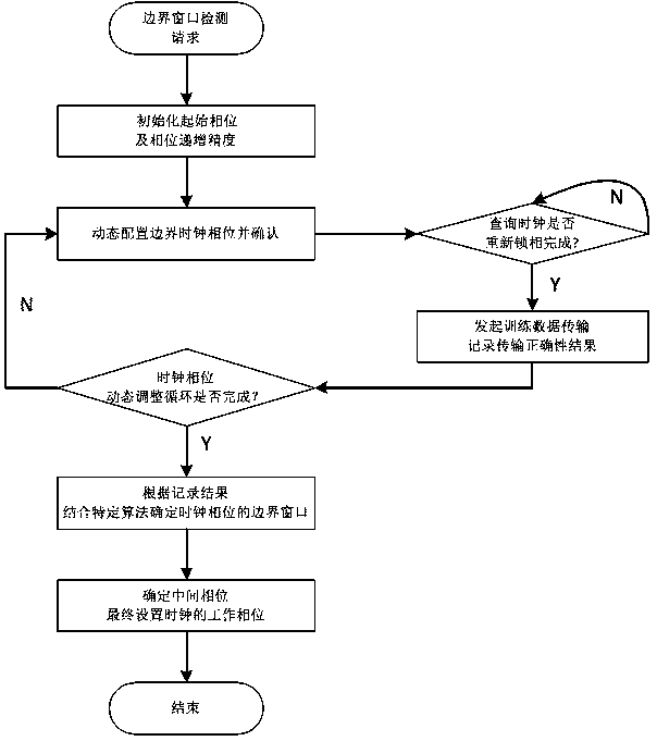
[0041] In this example, if figure 2 As shown, a method for determining the boundary clock window includes dynamic clock configuration: FPGA initializes dynamic clock configuration according to the dynamic configuration command; training data transmission: CPU queries the clock lock status information of FPGA and transmits training data to FPGA; phase cycle interval test : Traversing the entire phase cycle interval for dynamic clock configuration and transmission training; clock window determination: Obtain the transmission correctness test results returned by the FPGA, and re-initiate clock locking according to the test results to complete the clock window determination.

[0042] Specifically, a method for determining a boundary...


PUM


Abstract

The invention discloses a boundary clock window determination method. The method comprises the following steps: dynamic clock configuration: enabling an FPGA to initialize dynamic clock configurationaccording to a dynamic configuration command; training data transmission: enabling a CPU to query clock locking state information of the FPGA and transmit training data to the FPGA; phase cycle section testing: traversing the whole phase cycle section to perform dynamic clock configuration and transmission training; and clock window determination: obtaining a transmission correctness test result returned by the FPGA, and re-initiating clock locking according to the test result to complete clock window determination. Dynamic configuration of clock phases is completed by utilizing dynamic configuration interfaces of clock resources, such as PLL provided by the FPGA in cooperation with simple software and hardware logic functions. The design is simple, and certain self-adaptability is achieved. The method has a deserved value when the clock window of the medium-low speed parallel inter-chip interconnection bus is determined.

Description

technical field [0001] The invention relates to the field of clock window determination, in particular to a boundary clock window determination method, circuit, terminal equipment and storage medium. Background technique [0002] There are a large number of parallel synchronous bus interconnections in embedded systems, including between embedded CPU and peripherals, between FPGA and FPGA, and between FPGA and embedded CPU. Interconnection channels that support the interaction of these chip-level units all have the need to determine the clock window. like figure 1 As shown, sampling Data when the clock Clk is at point A is at the Tsetup boundary, and sampling Data when the clock Clk is at point B is at the Tholdon boundary. That is, when Clk is in any position between A and B, Data can be sampled reliably, so the window between A and B is the best window of Clk. [0003] In the actual project design, the determination of points A and B has a great relationship with the ado...

Claims


Application Information

Patent Timeline
Patent Type & Authority Applications(China)
IPC IPC(8): G06F13/42
CPCG06F13/4204
Inventor 索艳滨
Owner 成都三零嘉微电子有限公司
Why Eureka
Try Eureka