Electromechanical control cabinet

A control cabinet and electromechanical technology, applied in the field of control cabinets, can solve the problems of complicated control cabinet lines, no focus point, inconvenient handling, etc., and achieve the effect of increasing ventilation effect, increasing service life and simple operation

Inactive Publication Date: 2020-05-12
NORTHWEST A & F UNIV
View PDF0 Cites 3 Cited by
  • Summary
  • Abstract
  • Description
  • Claims
  • Application Information

AI Technical Summary

Problems solved by technology

[0002] The control cabinet is to assemble the switchgear, measuring instrument, protective device and auxiliary equipment in the closed or semiclosed metal cabinet or on the screen width according to the requirements of electrical wiring. And the safety of the surrounding equipment, the circuit can be connected or broken by manual or automatic switch during normal operation, and the circuit can be cut off or alarmed by means of protective electrical appliances in case of failure or abnormal operation, and various parameters in operation can be displayed by means of measuring instruments. Some electrical parameters are adjusted to prompt or send out signals for deviations from normal working conditions, which are often used in various power generation, distribution and substations; traditional electromechanical control cabinets have many shortcomings. First, there is a lot of dust in the workshop, and the dust is easy to pass through the panel Entering the inside of the control cabinet will affect the service life of the equipment. Secondly, the circuit of the control cabinet is complex and generates heat during operation. If the heat cannot be dissipated in time, the equipment will be easily damaged. In addition, because the control cabinet is large in size and has no focus, it is very inconvenient to carry. Therefore, We propose this electromechanical control cabinet

Method used


Image

  • Electromechanical control cabinet
  • Electromechanical control cabinet
  • Electromechanical control cabinet

Examples


Embodiment Construction

[0017] In order to make the technical means, creative features, goals and effects achieved by the present invention easy to understand, the present invention will be further described below in conjunction with specific embodiments.

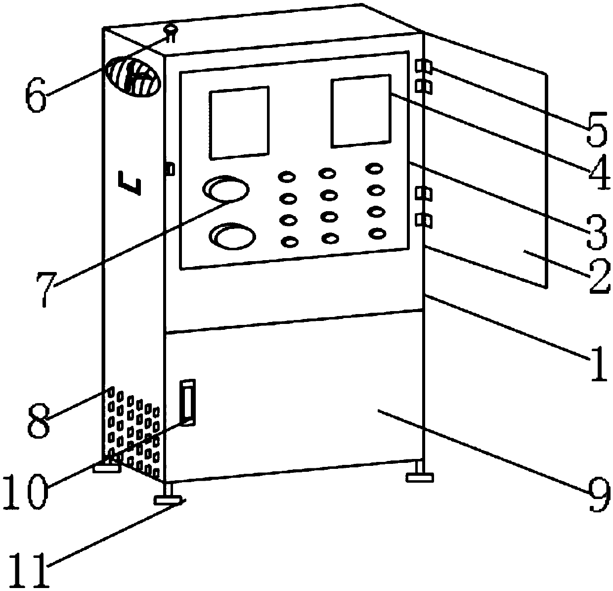
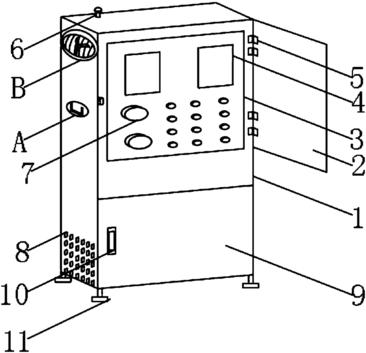
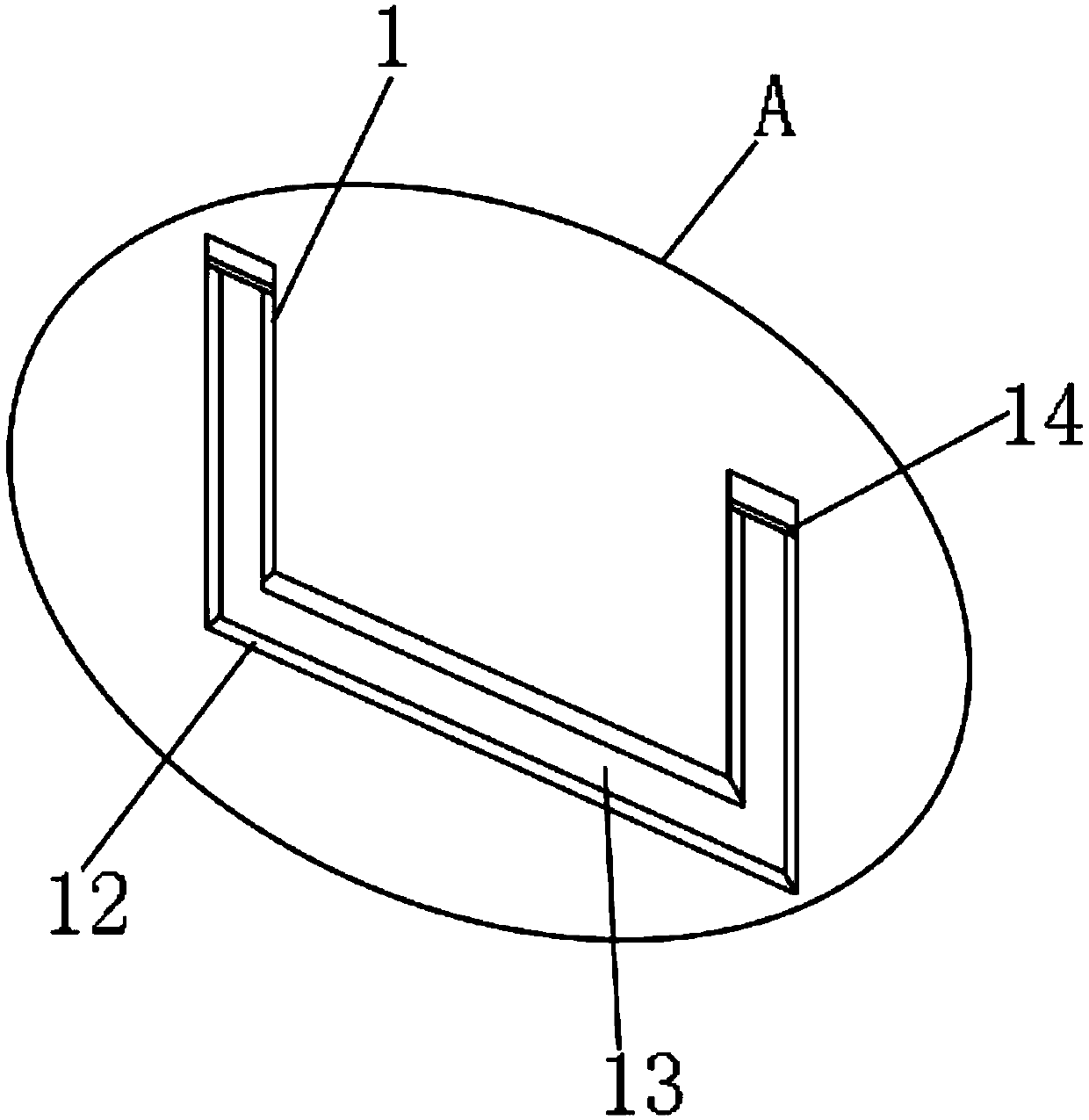
[0018] like Figure 1-4 As shown, an electromechanical control cabinet includes a control cabinet main body 1, a dust cover 2 is arranged at one end of the control cabinet main body 1, a control panel 3 is arranged on the front outer surface of the control cabinet main body 1, and a front outer surface of the control panel 3 is arranged There is a display screen 4, a hinge 5 is provided between the control cabinet main body 1 and the dust cover 2, the other end of the control cabinet main body 1 is provided with a mounting groove 12, and a handle 13 is provided inside the mounting groove 12, and the handle 13 is connected to the A movable shaft 14 is arranged between the control cabinet main body 1, and a rotating shaft 15 is arranged on the outer...


PUM


Abstract

The invention discloses an electromechanical control cabinet, which comprises a control cabinet main body, wherein a dustproof cover is arranged at one end of the control cabinet main body, a controlpanel is arranged on the outer surface of the front end of the control cabinet main body, a display screen is arranged on the outer surface of the front end of the control panel, a hinge is arranged between the control cabinet main body and the dustproof cover, and a mounting groove is formed in the other end of the control cabinet main body. According to the invention, dust can be prevented fromentering the equipment from the control panel, so that the service life of the equipment is prolonged; the control cabinet is convenient to carry, and the grip can be accommodated in the mounting groove, so that the control cabinet is simple to operate and does not occupy space; hot air generated in the control cabinet main body can be discharged into air to improves the ventilation effect of theequipment, so that the influence of high temperature generated inside on the operation of the equipment can be prevented; and workers can be prevented from hurting caused fan blades during rotation, so that the electromechanical control cabinet is safe, and can bring a good application prospect.

Description

technical field [0001] The invention relates to the field of control cabinets, in particular to an electromechanical control cabinet. Background technique [0002] The control cabinet is to assemble the switchgear, measuring instrument, protective device and auxiliary equipment in the closed or semiclosed metal cabinet or on the screen width according to the requirements of electrical wiring. And the safety of the surrounding equipment, the circuit can be connected or broken by manual or automatic switch during normal operation, and the circuit can be cut off or alarmed by means of protective electrical appliances in case of failure or abnormal operation, and various parameters in operation can be displayed by means of measuring instruments. Some electrical parameters are adjusted to prompt or send out signals for deviations from normal working conditions, which are often used in various power generation, distribution and substations; traditional electromechanical control ca...

Claims


Application Information

Patent Timeline
IPC IPC(8): H02B1/28H02B1/56
CPCH02B1/28H02B1/565
Inventor 刘世浩朱悦马驰
Owner NORTHWEST A & F UNIV
Why Eureka
Try Eureka