Electric shock pest killing device for automatic crop pest monitoring and reporting system

An insecticidal device and a technology for crops, which are applied in the device, application, animal husbandry and other directions of capturing or killing insects, can solve the problems of high power consumption, high cost, complex structure, etc., reduce the overlap rate and save energy. , the effect of easy identification

Pending Publication Date: 2020-05-15
刘嘉津
View PDF0 Cites 0 Cited by
  • Summary
  • Abstract
  • Description
  • Claims
  • Application Information

AI Technical Summary

Problems solved by technology

Among them, the method of heating and killing insects consumes a lot of power, which brings obstacles to the direct adoption of solar or wind power; the method of poisoning insects with drugs will have adverse effects on the environment and operators
In addition, the traditional crop pest detection and reporting lamp is a sampling inspection device, but its volume is several times larger than that of similar insecticidal lamp equipment, with complex structure and high cost.
[0

Method used


Image

  • Electric shock pest killing device for automatic crop pest monitoring and reporting system
  • Electric shock pest killing device for automatic crop pest monitoring and reporting system
  • Electric shock pest killing device for automatic crop pest monitoring and reporting system

Examples


Embodiment 1

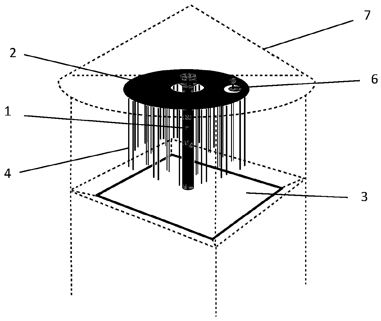
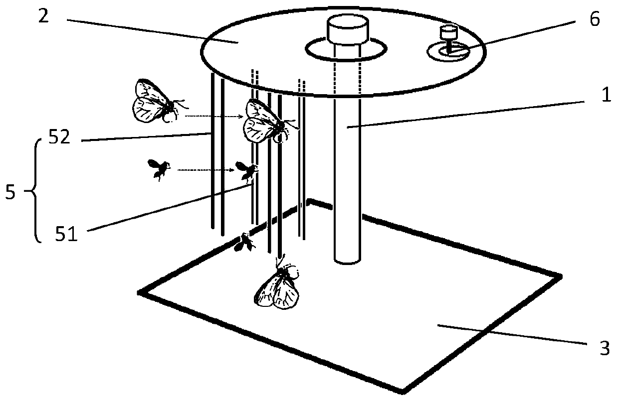
[0061] See attached Figure 1-4 , this embodiment discloses an electric shock killing device for an automatic pest detection and reporting system for crops, including an insect trap lamp 1, an insulating platform 2, an insect receiving platform 3, and an inner and outer two-layer electric pole arranged in sequence on the periphery of the insect trap lamp. The pole group 5, wherein the inner pole group 5 is composed of a plurality of first pole groups 51, the outer pole group 5 is composed of a plurality of second pole groups 52, and the insulating platform 2 is equipped with an eccentric shaft motor 6, wherein each Each pole group 5 is made up of two DC poles 4 each being a positive pole and a negative pole.

[0062] The insect trap lamp 1 passes through the insulating platform 2 and is fixed on the rainproof cover 7 on the top of the forecasting system, and each DC pole 4 is vertically fixed on the insulating platform 2, and there is a gap between the bottom of the DC pole 4 ...

Embodiment 2

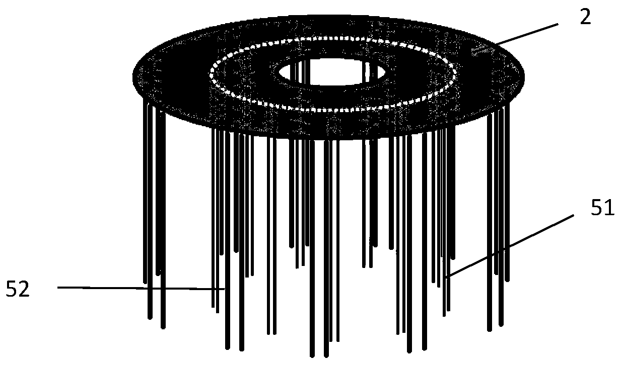
[0065] See attached Figure 5 , this embodiment discloses an electric shock insecticidal device used in an automatic pest detection and reporting system for crops, including an insect trap lamp 1, an insulating platform 2, an insect receiving platform 3, and three-layer electric poles arranged in sequence on the periphery of the insect trap lamp Group 5, wherein the inner pole group 5 is composed of a plurality of first pole groups 51, the outer pole group 5 is composed of a plurality of second pole groups 52, and the middle pole group 5 is composed of first An electric pole group 51 and a second electric pole group 52 are formed. The insulating platform 2 is equipped with an eccentric shaft motor 6, wherein each electric pole group 5 is composed of two DC electric poles 4 each being a positive pole and a negative pole.

[0066] The insect trap lamp 1 passes through the insulating platform 2 and is fixed on the rainproof cover 7 on the top of the forecasting system, and each D...


PUM


Abstract

The present invention discloses an electric shock pest killing device for an automatic crop pest monitoring and reporting system. The electric shock pest killing device comprises a trapping lamp, an insulating platform, a pest receiving platform and a plurality of electric pole groups; each electric pole group is composed of two direct-current electric poles as a positive electrode and a negativeelectrode, and the plurality of electric pole groups are vertically arranged around the trapping lamp; the trapping lamp penetrates through the insulating platform and is fixed to the top of the monitoring and reporting system, each direct-current electric pole is vertically fixed on the insulating platform, and a gap is reserved between the bottom of each direct-current electric pole and the pestreceiving platform; and the insulating platform is provided with an eccentric shaft motor, so that the insulating platform can drive all the electric poles to vibrate leftwards and rightwards simultaneously. While automatic identification of insect sample image acquisition conditions by crop pests is facilitated, equipment is simplified and the energy consumption is reduced, so that the automaticcrop pest monitoring and reporting system can be popularized in a large area by utilizing solar energy or wind energy.

Description

technical field [0001] The invention relates to the technical field of agricultural insects and pest control, and more specifically relates to an electric shock insecticidal device used in an automatic detection and reporting system for crop pests. Background technique [0002] Driven by my country's agricultural technology market, traditional crop protection monitoring is in the process of shifting from manual forecasting to automatic forecasting, and the application of crop pest automatic forecasting system is in its infancy. At present, the popularization of related equipment is restricted by various conditions. The most serious problem is the large energy consumption. The whole machine is generally above 200W. The equipment installation cannot be separated from the AC power grid. Therefore, there is no power grid in large-scale farmland or remote mountain forests. down does not work. [0003] Traditional crop pest forecasting lamps mainly include two methods of killing ...

Claims


Application Information

Patent Timeline
IPC IPC(8): A01M1/04A01M1/22
CPCA01M1/04A01M1/223A01M2200/012
Inventor 刘嘉津
Owner 刘嘉津
Why Eureka
Try Eureka