Supercharge Your Innovation With Domain-Expert AI Agents!

Liquid separation device

A technology of liquid separation device and liquid distribution device, which is applied in the direction of centrifuge, etc., to achieve the effect of simple operation and convenient use

Pending Publication Date: 2020-05-15
贵永平
View PDF2 Cites 0 Cited by
  • Summary
  • Abstract
  • Description
  • Claims
  • Application Information

AI Technical Summary

Problems solved by technology

[0005] However, in the prior art, there is still a need for a liquid separation device with convenient operation and accurate separation.

Method used


Image

  • Liquid separation device
  • Liquid separation device
  • Liquid separation device

Examples


Embodiment 1

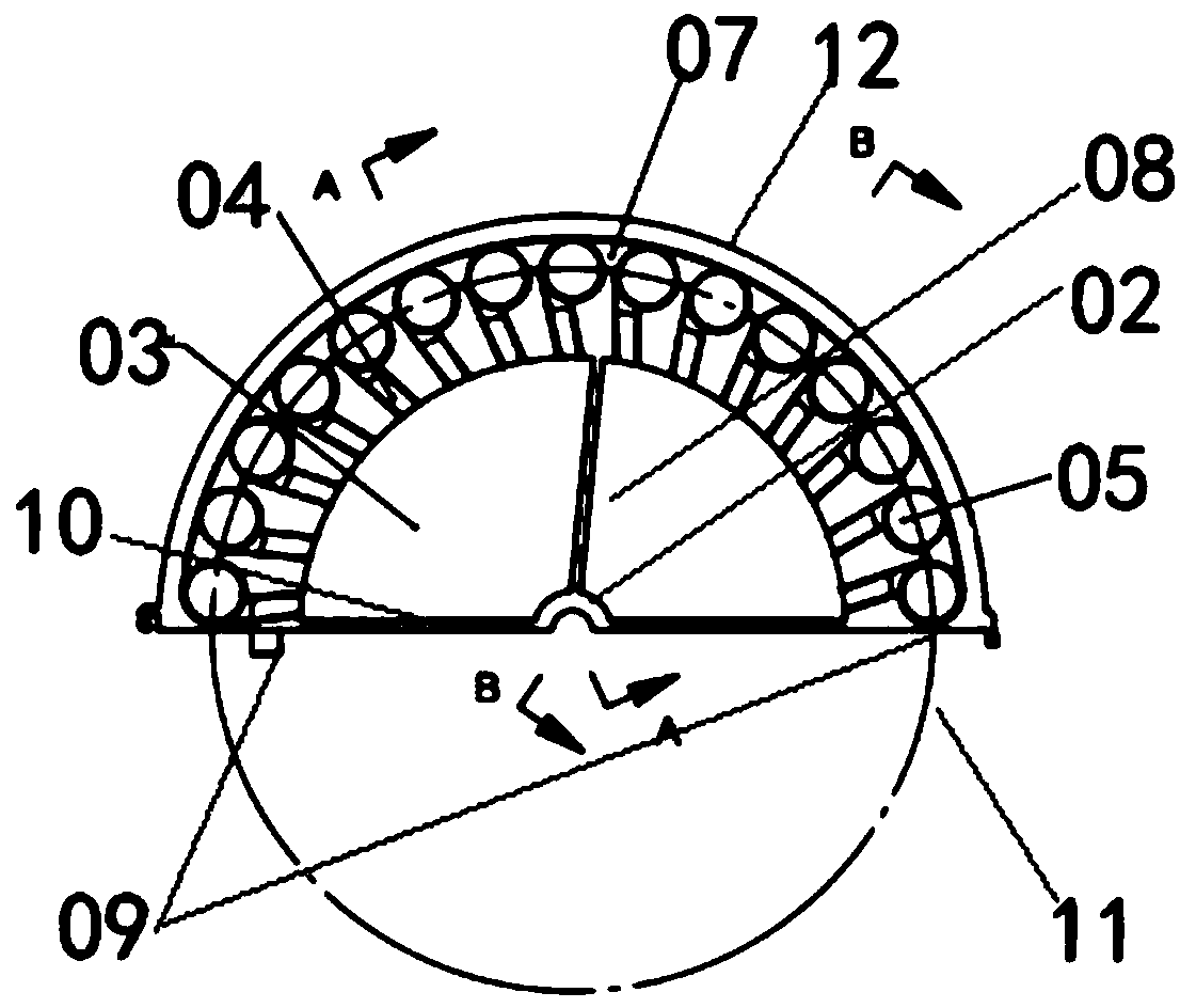
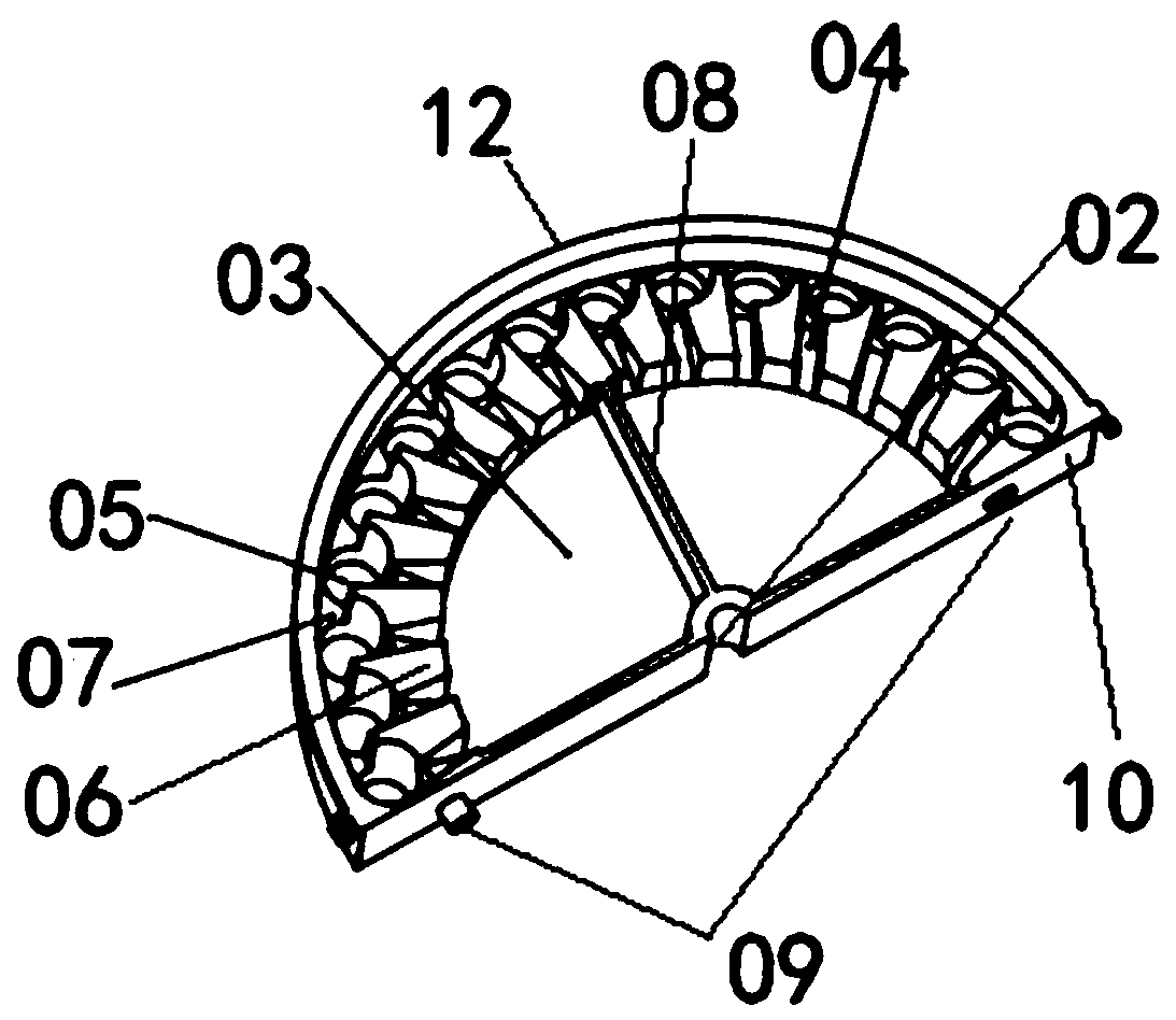
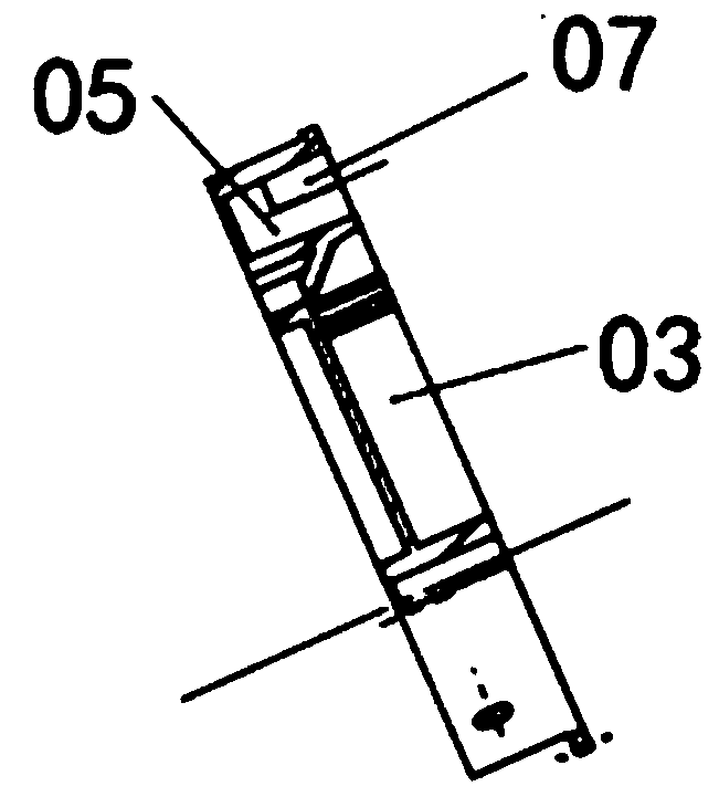
[0022] A semicircular liquid separation device such as figure 1 front view of figure 2 stereogram of image 3 and Figure 4 As shown in the cross-sectional diagram of , including 01 disk, 02 socket, 03 sample storage place, 04 liquid flow channel, 05 separation sample storage tank, 06 protrusion, 07 Unicom flow channel, 08 partition plate, 09 buckle, 10 Assembled board, the 01 disc includes 11 bases and 12 disc walls, the 02 jack is located at the center of the 01 disc and runs through the 01 disc, the 03 sample storage place is set around the 02 jack, the The 05 separation sample storage tank is set around the edge of the 01 disc, the 06 protrusion is set between the 03 sample storage place and the 05 separation sample storage tank, and the 04 liquid flow channel is formed between the adjacent 06 protrusions. The 10-piece board includes 09 buckles, and the 09 buckles are located at both ends of the diameter of the semicircular liquid separation device.

[0023] The semic...

Embodiment 2

[0026] A circular liquid separation device is formed by combining two semicircular liquid separation devices in Embodiment 1 through buckles.

[0027] When it is necessary to separate the liquid sample, install the liquid separation device on the centrifugal device through the 02 socket, place the liquid sample in the 03 sample storage place, turn on the centrifugal device, the 01 disc starts to rotate, and the samples in the 03 sample storage place are under centrifugal force. Under the action of the liquid, it moves toward the edge, and passes through the 04 liquid channel formed between the 06 protrusions, and finally flows into the 05 separation sample storage tank.

[0028] When there are enough liquid samples in the 05 separation sample storage tank, multiple samples overflowing from the separation sample storage tank are connected and mixed through the 07 communication channel.


PUM


Abstract

The invention discloses a liquid separation device. The liquid separation device comprises a disc, an inserting hole, a sample storage position, a liquid flow channel, a separated sample storage groove and protrusions, the sample storage position, the liquid flow channel, the separated sample storage groove and the protrusion are arranged in the disc, the disc comprises a base and a disc wall, theinserting hole is located in the center of the disc and penetrates through the disc, the sample storage position is arranged around the inserting hole, the separated sample storage groove is formed around the edge of the disc, the protrusions are arranged between the sample storage position and the separated sample storage groove, and the liquid flow channel is formed between the adjacent protrusions. According to the liquid separation device, separating one liquid can be carried out, separating a plurality of liquids can be carried out at the same time, mixing different separated samples canbe carried out after separation, the operation is simple, and the use is convenient.

Description

technical field [0001] The invention relates to the field of sample separation, in particular to a liquid separation device. Background technique [0002] Biochemical testing usually requires rapid quantitative distribution of liquids to perform different testing tasks. At the same time, biochemical detection usually requires the separation of components that may affect each other before detection. These quantitative partitioning and separation steps are usually achieved by centrifugation steps. Using centrifugal force to control fluid flow has many advantages, such as wide application range, convenient control, and high reliability. However, there are still many problems in the current centrifugal device, such as poor control accuracy, not convenient enough, unable to accurately and reliably transport, stop and discharge the sample to the designated position, etc. [0003] CN109694808A discloses a DNA extraction centrifugal disc, including at least one DNA extraction uni...

Claims


Application Information

Patent Timeline
IPC IPC(8): B04B5/12B04B7/00
CPCB04B5/12B04B7/00
Inventor 贵永平
Owner 贵永平
Features
  • R&D
  • Intellectual Property
  • Life Sciences
  • Materials
  • Tech Scout
  • Unparalleled Data Quality
  • Higher Quality Content
  • 60% Fewer Hallucinations
Learn More