Handheld type steel bar shearing and bending machine

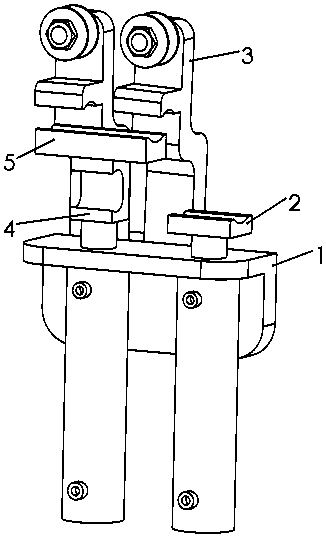
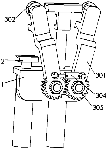
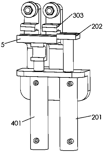
A shear bending and bending technology, which is applied in the field of hand-held steel bar shearing and bending machines, can solve the problems that the angle of the two bending sticks cannot be adjusted, there is no steel bar bending machine, and the work efficiency is reduced, so as to reduce the types of tools, facilitate operation, Easy bending effect

Active Publication Date: 2020-05-15
暴伟杰
View PDF12 Cites 0 Cited by
  • Summary
  • Abstract
  • Description
  • Claims
  • Application Information

AI Technical Summary

Problems solved by technology

[0004] After using the existing hand-held steel bar bending machine for a long time, it is found that the existing hand-held steel bar bending machine can only bend upwards or downwards alone, and there is no steel bar bending machine that can bend both upwards and downwards, and The angle of the two bending sticks of the existing steel bending machine cannot be adjusted, which is very inconvenient to use, and when the steel bar needs to be cut, a special steel bar shearing machine is required to cut the steel bar, and the back and forth operation of various machines reduces the work efficiency , is not conducive to the development of work;

Method used


Image

  • Handheld type steel bar shearing and bending machine
  • Handheld type steel bar shearing and bending machine
  • Handheld type steel bar shearing and bending machine

Examples


Embodiment Construction

[0033] The technical solutions of the present invention will be further specifically described below through the embodiments and in conjunction with the accompanying drawings. In the following description, many specific details are set forth in order to fully understand the present invention, but the present invention can be implemented in many other ways different from those described here, and those skilled in the art can do similar Modifications, and therefore the present invention is not limited to the specific examples disclosed below.

[0034] In the description of the present invention, it should be noted that the orientation or positional relationship indicated by the terms "up", "down", "front", "rear", "left", "right" etc. are based on the Orientation or positional relationship, or the orientation or positional relationship that the inventive product is usually placed in use, is only for the convenience of describing the present invention and simplifying the descript...


PUM


Abstract

A steel bar shearing and bending machine comprises a base part, a shearing knife part, a swing arm part, a bending groove part and a shearing clamping groove, a steel bar to be sheared is fixed in a shearing fixing groove of the swing arm part through the shearing clamping groove, the steel bar is cut off through the shearing knife part, and the steel bar to be bent and placed on a bending rod isbent through a bending groove, so that the functions of shearing and bending are integrated, meanwhile, the opening angles of two swing arms can be adjusted according to actual conditions, the steel bar to be bent can be bent upwards or downwards according to requirements, the use is convenient, and the working efficiency is improved.

Description

technical field [0001] The invention relates to the technical field of construction engineering equipment and electric hydraulic tools, in particular to a hand-held steel bar shearing and bending machine. Background technique [0002] In the process of building construction, it is often necessary to cut and bend the steel bars. The shearing and bending of the steel bars can be divided into two situations. One is to use heavy machinery on the ground to cut and bend the steel bars according to the theoretical design before construction. , for example, the Chinese invention patent No. 2017101844896 discloses a steel bar bending machine, which includes a workbench, a workpan arranged on the workbench, and an iron stopper shaft arranged on one side of the workdisk. The iron stopper shaft is far away from the work One end of the plate is provided with a clamping mechanism for clamping the steel bar; and a water bag is set on the side wall of the storage tank, and the force of the ...

Claims


Application Information

Patent Timeline
Patent Type & Authority Applications(China)
IPC IPC(8): B21F1/00B21F11/00B23D29/02
CPCB21F1/00B21F11/00B23D29/023
Inventor 暴伟杰高峰刘兵魏石磊
Owner 暴伟杰
Why Eureka
Try Eureka