Steel assemblage clamping device

A clamping device and assembly technology, which is applied in the field of auxiliary equipment for section steel production, can solve problems such as cumbersome positioning operations and inconvenient welding, and achieve the effect of improving efficiency

Active Publication Date: 2020-05-15
重庆实创钢结构有限公司
View PDF5 Cites 0 Cited by
  • Summary
  • Abstract
  • Description
  • Claims
  • Application Information

AI Technical Summary

Problems solved by technology

[0003] The object of the present invention is to provide a steel assembly vertical clamping device to solve the problem of inconvenient welding due to cumbersome positioning operations in the production of medium-shaped steel in the prior art

Method used


Image

  • Steel assemblage clamping device
  • Steel assemblage clamping device
  • Steel assemblage clamping device

Examples


Embodiment 1

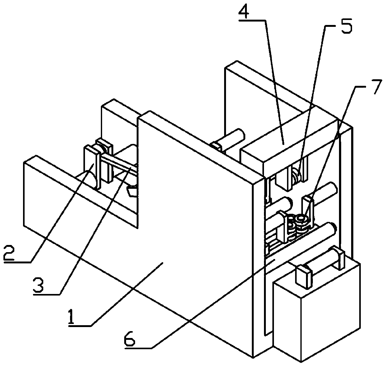
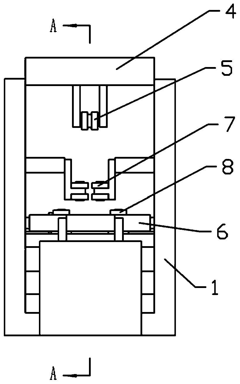
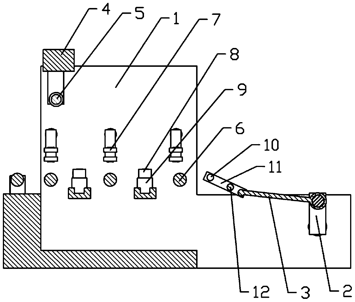
[0023] Embodiment one: if Figure 1 to Figure 5 As shown: a vertical clamping device for a steel group, including a bracket 1, on which three supporting rollers 6 arranged horizontally are rotatably connected, and the three supporting rollers 6 are horizontally arranged side by side; the gap between adjacent supporting rollers 6 is provided with a first 8 sets of positioning wheels, the first 8 sets of positioning wheels include two first sliders 9 arranged in gaps, and the two first sliders 9 are slidably connected with the bracket 1 along the axial direction of the support roller 6, and the two first sliders 9 are The sides away from each other are rotatably connected with screw rods, the axial direction of the screw rods is parallel to the axial direction of the support roller 6, and the end of the screw rods away from the first slider 9 is threadedly connected with the support 1; the two first sliders 9 are rotatably connected There is a first positioning wheel 8 whose axi...

Embodiment 2

[0027] Embodiment 2: The difference from Embodiment 1 is only that a torsion spring is provided at the hinge between the clamping frame 11 and the connecting rod 3, and the clamping frame 11 makes the upper nip roller 10 always have the principle under the action of the torsion spring. The trend of the connecting rod 3; the upper nip roller 10 and the clamping frame 11 are connected by a one-way bearing, and the upper nip roller 10 can only rotate counterclockwise under the action of the one-way bearing, so that the connecting rod 3 can push the clamp When the holder 11 moves, it is convenient for the upper nip roller 10 to pass over the welding spot 15, and when the pull rod pulls the gripper 11, the upper nip roller 10 cannot rotate, which is beneficial to increase the effect between the upper nip roller 10 and the welding spot 15 force, to ensure that the clamping part drives the wing plate 14 and the web plate 13 to move through the welding spot 15.


PUM


Abstract

The invention belongs to the technical field of auxiliary equipment for profile steel manufacturing and particularly discloses a steel assemblage clamping device. The steel assemblage clamping devicecomprises a support; a plurality of supporting rollers which are arranged transversely are rotationally connected to the support; the tops of all the supporting rollers are located on the same plane;a first positioning wheel set and a second positioning wheel set are rotationally connected to the support; the rotation axis of the first positioning wheel set is parallel to that of the second positioning wheel set; a tight pressing wheel is further disposed above the supporting wheels, and the axis of the tight pressing wheel is parallel to the axes of the supporting rollers; and a feeding mechanism is disposed on the support. By means of the scheme, the problem that in the prior art, welding is inconvenient due to complicated positioning operation during profile steel manufacturing is solved.

Description

technical field [0001] The invention belongs to the technical field of auxiliary equipment for section steel production, in particular to a clamping device for steel assembly. Background technique [0002] Steel assembly refers to the operation of assembling plates into steel. When making H-shaped steel, it is necessary to assemble and position the steel plates used to make the flange and web of the H-shaped steel, and then use local spot welding for preliminary shaping. In the existing method, the steel plate of the H-shaped steel is generally positioned by means of a stereotyped tooling, and then the welding operation is performed. When using tooling for positioning, it is necessary to set a tooling of appropriate length according to the length of the H-beam, and after positioning, the pressure mechanism needs to apply a certain pressure to make the web and the wing plate close together, so as to avoid gaps and change the size of the H-beam after forming; After the weldi...

Claims


Application Information

Patent Timeline
Patent Type & Authority Applications(China)
IPC IPC(8): B23K37/04B23K103/04
CPCB23K37/0443B23K2103/04
Inventor 谢家凤谢亮徐乔
Owner 重庆实创钢结构有限公司
Why Eureka
Try Eureka