Control system of unmanned aerial vehicle capable of vertically taking off and landing

A vertical take-off and landing and control system technology, applied in vertical take-off and landing aircraft, aircraft control, unmanned aircraft, etc., can solve the problems of high cost of use, strict requirements for take-off conditions, single function, etc., and achieve convenient loading and unloading , save driving energy consumption, and facilitate take-off and landing

Inactive Publication Date: 2020-05-15
BEIJING UNIV OF CIVIL ENG & ARCHITECTURE
View PDF8 Cites 5 Cited by
  • Summary
  • Abstract
  • Description
  • Claims
  • Application Information

AI Technical Summary

Problems solved by technology

Limited by the development of battery technology, the battery life of multi-rotor drones, high altitude, and long-distance performance are not good.
Traditional fixed-wing aircraft have the characteristics of heavy load and long endurance, but they have strict requirements for take-off conditions, and often require a long distance for taxiing
[0004] Existing fixed-wing aircraft that can take off and land vertically have single functions and insufficient battery life
However, fixed-wing UAVs have relatively large take-off and landing restrictions, are difficult to apply in a wide range, and cannot quickly carry various equipment, and the cost of use is high.

Method used


Image

  • Control system of unmanned aerial vehicle capable of vertically taking off and landing
  • Control system of unmanned aerial vehicle capable of vertically taking off and landing
  • Control system of unmanned aerial vehicle capable of vertically taking off and landing

Examples


Embodiment Construction

[0042] In order to make the purpose and technical solutions of the embodiments of the present invention more clear, the technical solutions of the embodiments of the present invention will be clearly and completely described below in conjunction with the drawings of the embodiments of the present invention. Apparently, the described embodiments are some, not all, embodiments of the present invention. Based on the described embodiments of the present invention, all other embodiments obtained by persons of ordinary skill in the art without creative efforts shall fall within the protection scope of the present invention.

[0043] Those skilled in the art can understand that, unless otherwise defined, all terms (including technical terms and scientific terms) used herein have the same meaning as commonly understood by those of ordinary skill in the art to which this invention belongs. It should also be understood that terms such as those defined in commonly used dictionaries shoul...


PUM


Abstract

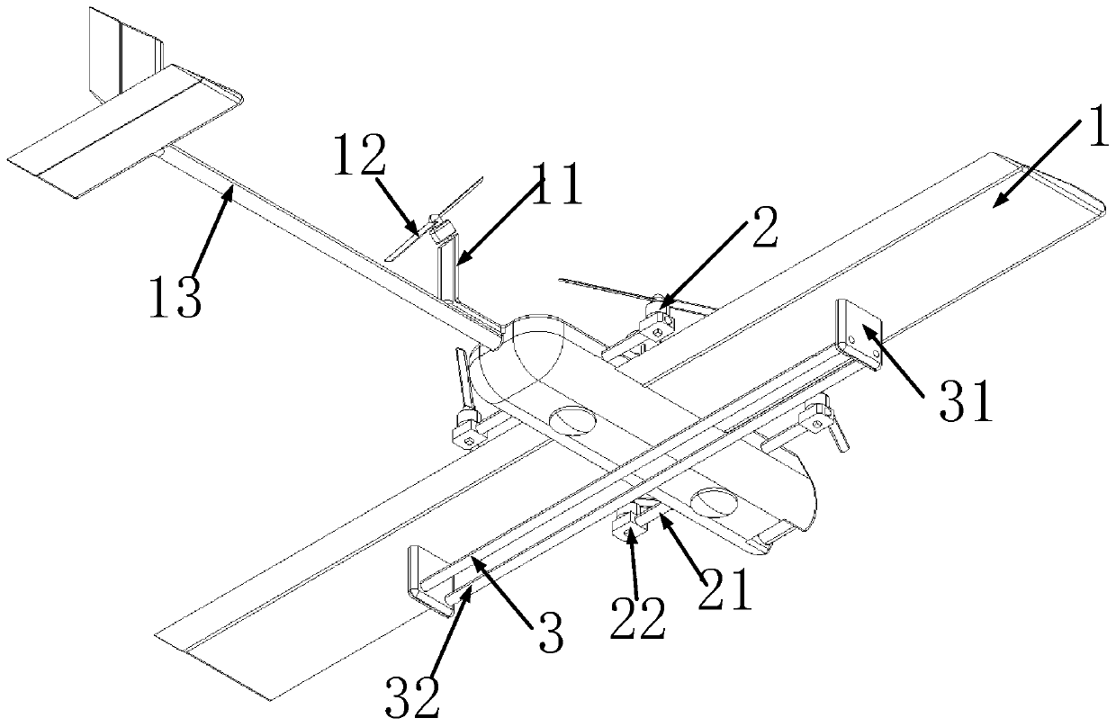
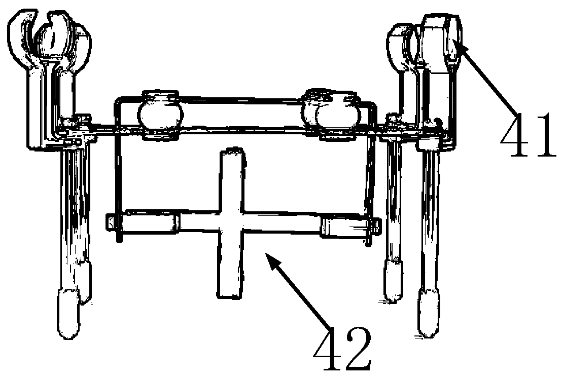
The invention provides a control system of an unmanned aerial vehicle capable of vertically taking off and landing. A fixed wing system and a vertical take-off and landing system are arranged on the unmanned aerial vehicle body at the same time, the unmanned aerial vehicle is controlled to operate in a vertical take-off and landing mode during take-off and landing, and take-off or landing is achieved through the vertical take-off and landing system; in the process that the unmanned aerial vehicle rises to a certain height and flies, the unmanned aerial vehicle is controlled to operate in a fixed wing mode, driving force is output through an obliquely-arranged fixed wing propelling device to drive the unmanned aerial vehicle to fly, and driving energy consumption is reduced. According to the unmanned aerial vehicle control system provided by the invention, various external devices can be conveniently carried, loaded and unloaded, the energy consumption required by flight is lower, and due to the arrangement of the vertical take-off and landing system, take-off and landing can be conveniently carried out in a small space.

Description

technical field [0001] The invention relates to the field of flight equipment, in particular to a control system for an unmanned aerial vehicle capable of vertical take-off and landing. Background technique [0002] With the application of multi-rotor UAVs more and more widely, UAVs have begun to be well known. At the same time, unmanned aerial vehicles have begun to emerge in the civilian and commercial fields. But now all kinds of drones have their own advantages, and the advantages are different and have a single function. [0003] For example, multi-rotor drones, which are widely used at present, have the functions of vertical take-off and landing, hovering in the air, strong flexibility, and can complete flight tasks in a short distance range. Limited by the development of battery technology, the current multi-rotor UAVs have poor battery life, high altitude, and high long-distance performance. Traditional fixed-wing aircraft have the characteristics of heavy load an...

Claims


Application Information

Patent Timeline
Patent Type & Authority Applications(China)
IPC IPC(8): B64C27/26B64C27/28B64C29/00B64C19/00
CPCB64C27/26B64C27/28B64C29/00B64C19/00B64U10/25B64U30/10B64U10/10B64U50/19B64U2201/00B64U30/20B64U2101/00
Inventor 姚德臣杨建伟孙强张骄武向鹏刘恒畅寇子明
Owner BEIJING UNIV OF CIVIL ENG & ARCHITECTURE
Why Eureka
Try Eureka