Pallet box

A pallet box and support technology, applied in the field of machinery, can solve the problems of affecting operation safety, difficult processing, and lack of fixed locks, and achieve the effects of not destroying the coating, good safety, and easy processing

Pending Publication Date: 2020-05-15
高惠锦
View PDF0 Cites 0 Cited by
  • Summary
  • Abstract
  • Description
  • Claims
  • Application Information

AI Technical Summary

Problems solved by technology

Hot-dip galvanizing is a common surface treatment process for pallet boxes, but the locks on the pallet box generally cannot be hot-dip galvanized as a whole, otherwise it will cause missing plating of the locks and inflexible operation of the locks
[0003] At present, the locks of the two lock installation processes have the following problems: when the post-welded locks are used for hot-dip galvanized pallet boxes, the electro-galvanized locks need to be welded on the hot-dip galvanized frame, which will damage the galvanized layer. It needs to be repaired with paint, but the anti-corrosion ability and appearance of the repaired pallet box are affected; the lock rod and the lock seat are installed separately, the processing is difficult, the installation is troublesome, the cost of parts is high, and the strength of the lock rod is poor , the lock bar is easy to protrude out of the pallet box, and the security is poor
[0004] In addition, some locks are not fixed when they are opened, which may easily cause the handle to be lifted, which will affect the safety of operation.

Method used


Image

  • Pallet box
  • Pallet box
  • Pallet box

Examples


Embodiment Construction

[0056] In the following description, a lot of specific details are given in order to provide a more thorough understanding of the present invention. However, it is obvious to those skilled in the art that the embodiments of the present invention can be implemented without one or more of these details. In other examples, in order to avoid confusion with the embodiments of the present invention, some technical features known in the art are not described.

[0057] It should be noted that the terms "upper", "lower", "front", "rear", "left", "right", "inner", "outer" and similar expressions used in this article are for illustration only Purpose, not limitation.

[0058] The ordinal words such as "first" and "second" quoted in the present invention are merely identifications and do not have any other meanings, such as a specific order. Also, for example, the term “first component” itself does not imply the existence of “second component”, and the term “second component” does not imply ...


PUM


Abstract

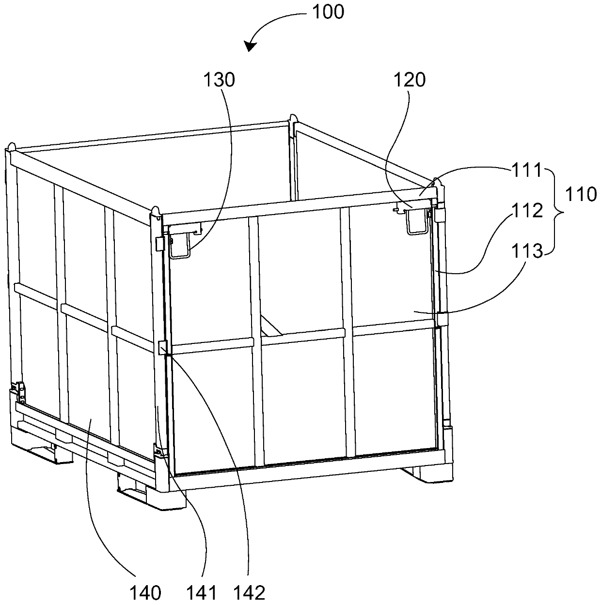
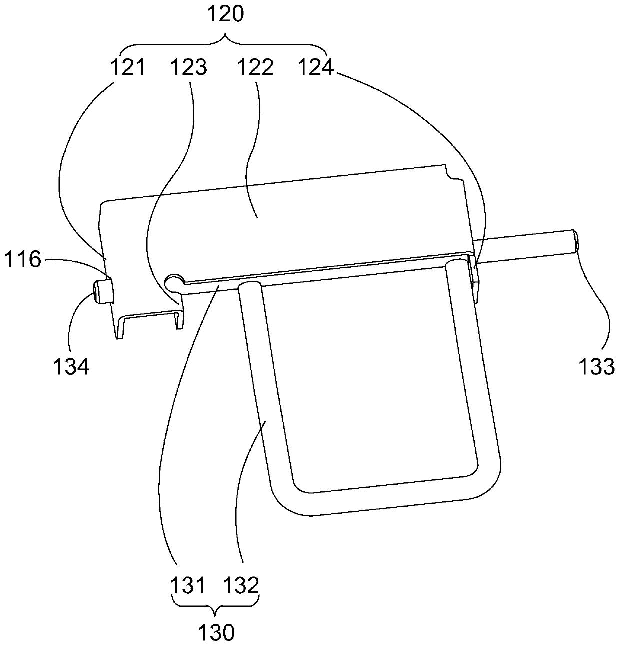
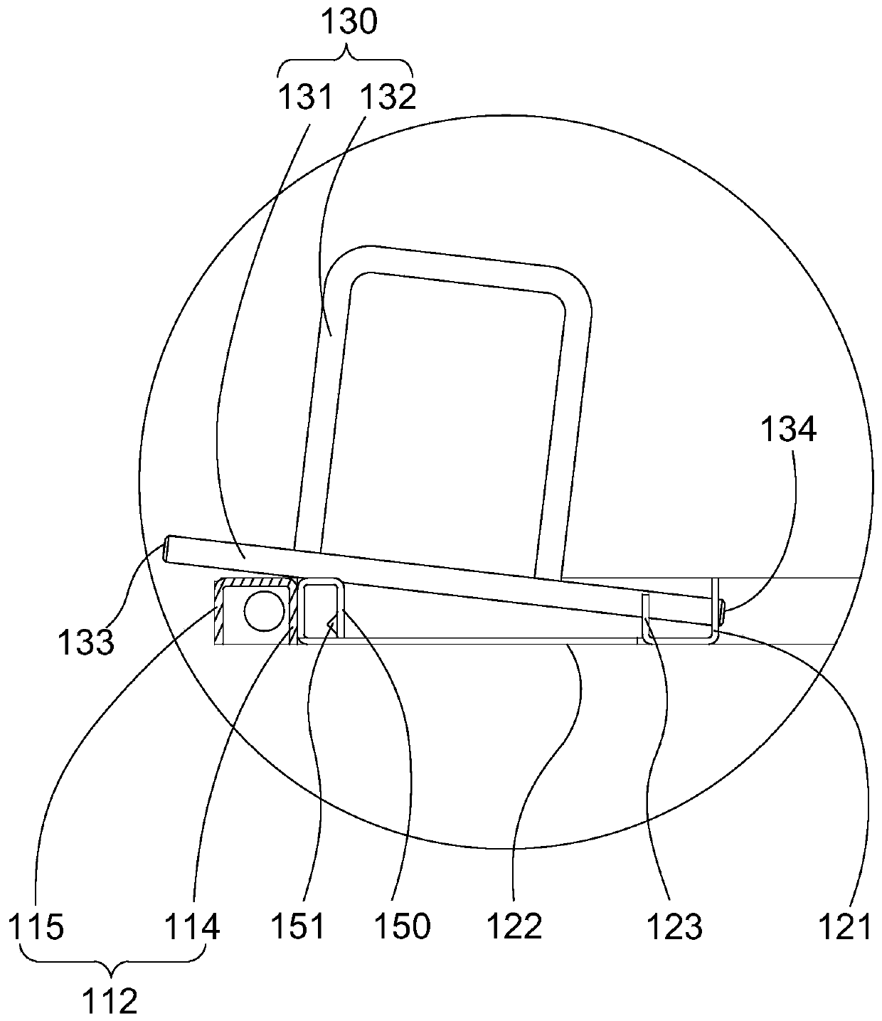
The invention provides a pallet box, which comprises an end wall, a locking rod and a locking seat. The end wall is provided with a frame and a shroud plate connected to the frame, and the frame is provided with a first locking hole; the locking rod comprises a rod body and a handle connected with the rod body, the rod body and the handle can overall rotate, a locking end penetrates through the first locking hole, and the locking rod can move between an opening position and a locking position; the locking seat is connected to the end wall and comprises a supporting part, a limiting part and ablocking part, the supporting part is provided with a supporting hole allowing a free end to penetrate, the limiting part is connected with the supporting part so as to limit the maximum rotating angle of the locking rod by limiting rotation of the handle, the blocking part is connected with the supporting part, and at least part of the blocking part is located below the locking rod so as to blockthe locking end from exiting from the first locking hole by blocking moving of the handle; and the shroud plate is connected to the front part of the frame, the handle can rotate towards the inner side of the pallet box and thus is prevented from intervening with the limiting part and the blocking part, and thus the free end can extend to penetrate through the supporting hole or exit from the supporting hole. The pallet box has the advantages that a lock is simple in structure, good in safety and the like.

Description

Technical field [0001] The invention relates to the field of machinery, in particular to a pallet box. Background technique [0002] There are two common installation methods for the locks of the hot-dip galvanized pallet box: one is to weld the electro-galvanized lock to the hot-dip galvanized pallet box parts, and then perform repair paint treatment; the other is to connect the lock seat to the pallet After the box parts are welded, hot-dip galvanized together, and then install the electro-galvanized or hot-dip galvanized lock rod on the lock seat. Hot-dip galvanizing is a common surface treatment process for pallet boxes, but the locks on the pallet boxes generally cannot be hot-dip galvanized as a whole, otherwise it will cause the locks to leak plating and the locks to operate inflexibly. [0003] The current locks of the two lock installation processes have the following problems: when the post-welded locks are used in hot-dip galvanized pallet boxes, the electro-galvanized ...

Claims


Application Information

Patent Timeline
IPC IPC(8): B65D19/08B65D19/38
CPCB65D19/08B65D19/38
Inventor 高惠锦
Owner 高惠锦
Why Eureka
Try Eureka